Spatially selective deposition of polysaccharide layer onto patterned template

Inactive Publication Date: 2006-05-18
MARYLAND BIOTECH INST UNIV OF +2
View PDF15 Cites 32 Cited by
  • Summary
  • Abstract
  • Description
  • Claims
  • Application Information

AI Technical Summary

Benefits of technology

[0096] Rehydration results in about a fourfold increase in film thickness and the observed changes in the film thickness were repeatable, i.e., the thicknesses of the nanoparticle-containing rehydrated films underwent minor change as the result of each of the f

Problems solved by technology

However, traditional approaches have not proven particularly successful in adequately bonding organic and biological materials to the patterned inorganic surfaces.
This first approach has several drawbacks: the required photo-sensitive reagents can be expensive and hazardous to use; additionally, cumbersome steps are required in order to prepare the surface.
Furthermore, conventional photolithographic operations require “line-of-sight” and cannot be readily employed on internal surfaces (such as in an enclosed microfluidic system).
Alternatively, if the lithographic patterning and subsequent biological functionalization are carried out before the microfluidic device is covered to form a closed fluidic environment, the biofunctionality internal to the microfluidic system cannot be readily reprogrammed.
Finally, since many biospecies are labile, i.e., sensitive and delicate with respect to their environmental conditions

Method used


Image

  • Spatially selective deposition of polysaccharide layer onto patterned template
  • Spatially selective deposition of polysaccharide layer onto patterned template
  • Spatially selective deposition of polysaccharide layer onto patterned template

Examples


example 1

[0072] The first example examined the selective deposition of fluorescently labeled chitosan onto a patterned surface. For this example, a silicon wafer was patterned to have two independent sets of gold surfaces. The photomicrographs in the top row of FIG. 5 were obtained using an optical microscope and show the patterns of the two sets of gold surfaces, with the right upper and left upper photomicrographs showing the gold surface patterns before and after deposition, respectively. The bottom row of photomicrographs of FIG. 5 was taken with a fluorescence microscope before and after deposition. The photomicrograph on left of the bottom row of FIG. 5 shows that prior to deposition, no image could be obtained from this patterned surface when a fluorescence microscope was used.

[0073] For deposition, the wafer was immersed in a solution containing the labeled chitosan and a negative voltage was applied to the polarizable gold surfaces. After 2 min of deposition, the wafer was removed ...

example 2

[0075] In the second example, unlabeled chitosan was deposited onto a patterned surface and examined the spatial selectivity for subsequent coupling reactions. For this example, a wafer was patterned to have a variety of gold lines with different widths and different spaces between the lines. The following table lists the dimensions of the various lines and spaces and shows that the lines vary in width from 20 to 1000 μm.

TABLELine thickness (μm)20501005001000Space (μm)50050050010001000100100200500500205010020030010305050100510101050

[0076] For deposition, this patterned wafer was immersed in a chitosan solution and the gold surface was polarized to be negative for 2 min. After deposition, the wafer was neutralized, rinsed, and dried as described above. Photomicrographs of the region of the wafer patterned with 1 mm wide gold lines spaced 1 mm apart were taken. The optical microscope showed both the lines and spaces in this region. No fluorescence was observed (through the fluoresce...

example 3

[0080] Chitosan from crab shells (15% deacetylation and a molecular weight of 200,000 as reported by the supplier) and glass slides coated with indium tin oxide (ITO) were purchased from Sigma-Aldrich Chemicals. Fluorescently labeled latex nanoparticles (FluoSpheres, 100 nm, excitation maximum 540nm and emission maximum 560 nm) and 5- (and 6-) carboxyfluorescein succinimidyl ester (NHS-fluorescein, excitation maximum 495 nm and emission maximum 519 nm) were purchased from Molecular Probes.

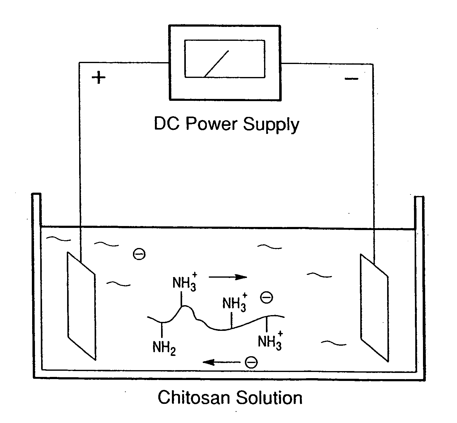
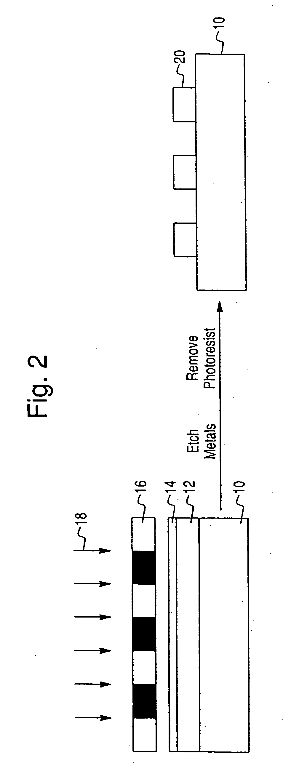
[0081] A chitosan solution was prepared by adding chitosan flakes to water and incrementally adding small amounts of HCl to the solution to maintain the pH near 3. After filtering undissolved material, the pH of the chitosan solution was adjusted to 5.0 using NaOH(1 M). Fluorescently labeled chitosan was prepared by reacting chitosan with NHS-fluorescein. Gold patterned silicon wafers were prepared using standard photolithographic methods. See, e.g., Wu, et al., Langmuir 2002, 18, 8620-8625; Wu et...


PUM

PropertyMeasurementUnit
Thicknessaaaaaaaaaa
Thicknessaaaaaaaaaa
Thicknessaaaaaaaaaa

Abstract

A method is provided for electrochemically depositing a polymer with spatial selectivity. A substrate having a substrate surface is contacted with an aqueous solution containing a selectively insolubilizable polysaccharide, such as chitosan, which is subjected to electrochemically treatment to deposit, with spatial selectivity, the selectively insolubilizable polysaccharide on a patterned electrically conductive portion of the substrate surface.

Description

CROSS-REFERENCE TO RELATED APPLICATIONS [0001] This application is a continuation-in-part of PCT / US03 / 40801 entitled “Spatially-Selective Deposition of Polysaccharide Layer onto Patterned Template,” filed Dec. 19, 2003, which is a continuation-in-part of PCT / US03 / 26356 entitled “Assembly of Chitosan onto an Electrode Surface,” filed Aug. 22, 2003), the complete disclosures of which are incorporated herein by reference; this application claims the benefit of priority of U.S. provisional application no. 60 / 434,958 filed Dec. 20, 2002 entitled “Spatially Selective Deposition of a Reactive Polysaccharide Layer onto a Patterned Template,” the complete disclosure of which is incorporated herein by reference.GOVERNMENT LICENSING CLAUSE [0002] The U.S. Government has a paid-up license in this invention and the right in limited circumstances to require the patent owner to license others on reasonable terms as provided for by the terms of Grant No. BES-01 114790 awarded by the National Scienc...

Claims


Application Information

Patent Timeline
IPC IPC(8): C25D5/02
CPCC08B37/003C09D5/4419C09D105/08C25D9/02
Inventor BENTLEY, WILLIAM E.GHODSSI, REZAPAYNE, GREGORY F.RUBLOFF, GARY W.WU, LI-QUNYI, HYUNMINLOSERT, WOLFGANGENGLISH, DOUGLAS S.
Owner MARYLAND BIOTECH INST UNIV OF
Why Eureka
Try Eureka