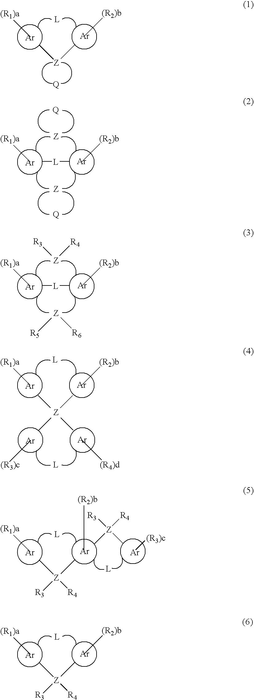
Organic electroluminescence devices
an electroluminescence device and organ technology, applied in the direction of discharge tube luminescnet screen, triarylamine dye, anthracene dye, etc., can solve the problems of short life, inadequacies for commercial use, and low temperature of materials, and achieve excellent heat resistance and high emission efficiency
- Summary
- Abstract
- Description
- Claims
- Application Information
AI Technical Summary
Benefits of technology
Problems solved by technology
Method used
Image
Examples
example 1
Fabrication of a Blue Light Emission Device
[0146] An indium tin oxide transparent electrode (thickness:120 nm) was formed on a glass substrate (25×75×1.1 mm). The glass substrate was cleaned through irradiation of a UV ray in an ozone atmosphere, and placed in a vacuum deposition apparatus.
[0147] On the electrode, 4,4′-bis(N,N-di-(3-tolyl)-4-aminophenyl)-4″-phenyltriphenylamine serving as a hole-injecting layer (thickness:60 nm), N,N-bis[4′-(N-(naphtyl-1-yl)-N-phenyl)aminobilhenyl-4-yl]-N-phenylamine (thickness:20 nm) were sequentially vapor-deposited, followed by simultaneously vapor-depositing the aforementioned Compound (B)-2 serving as a host material and the aforementioned Compound (A)-51 serving as a dopant (40:2 by weight) thereon, to thereby form a light-emitting layer (thickness:40 nm).
[0148] Subsequently, tris(8-hydroxyquinolinato)aluminum serving as an electron-injecting layer (thickness:20 nm) was deposited, followed by sequentially vapor-depositing lithium fluoride (...
example 2 to 7
[0150] The procedure of Example 1 was repeated, except that the compounds described in the Table 1 respectively serving as a host material and a dopant which were employed for the light-emitting layer were used, to thereby fabricate organic EL devices. When the fabricated devices were tested by passing electric current in a manner similar to that of Example 1, the results were described in Table 1.
example 8
Fabrication of a Green Light-Emitting Device
[0153] An indium tin oxide transparent electrode (thickness:80 nm) was formed on a glass substrate (25×75×1.1 mm). The glass substrate was cleaned through irradiation of a UV ray in an ozone atmosphere, and placed in a vacuum deposition apparatus.
[0154] On the electrode, 4,4′-bis(N,N-di-(3-tolyl)-4-aminophenyl)-4″-phenyltriphenylamine serving as a hole-injecting layer (thickness:60 nm), N,N-bis[4′-(N-(diphenylamino)phenyl)-N′,N″-diphenylbiphenyl-4,4′-diamine (thickness:20 nm) were sequentially vapor-deposited, followed by simultaneously vapor-depositing the aforementioned compound (B)-1 serving as a host material and the aforementioned Compound (A)-87 serving as a dopant (40:3 by weight) thereon, to thereby form a light-emitting layer (thickness:40 nm).
[0155] Subsequently, tris(8-hydroxyquinolinato)aluminum serving as an electron-injecting layer (thickness:20 nm) was deposited, followed by sequentially vapor-depositing lithium fluoride ...
PUM
| Property | Measurement | Unit |
|---|---|---|
| Electric potential / voltage | aaaaa | aaaaa |
| Electric potential / voltage | aaaaa | aaaaa |
| Electric potential / voltage | aaaaa | aaaaa |
Abstract
Description
Claims
Application Information
 - R&D
- Intellectual Property
- Life Sciences
- Materials
- Tech Scout
- Unparalleled Data Quality
- Higher Quality Content
- 60% Fewer Hallucinations
Browse by: Latest US Patents, China's latest patents, Technical Efficacy Thesaurus, Application Domain, Technology Topic, Popular Technical Reports.
© 2025 PatSnap. All rights reserved.Legal|Privacy policy|Modern Slavery Act Transparency Statement|Sitemap|About US| Contact US: help@patsnap.com


