Diamond composite heat spreaders having low thermal mismatch stress and associated methods

Inactive Publication Date: 2006-06-01
SUNG CHIEN MIN
View PDF57 Cites 93 Cited by
  • Summary
  • Abstract
  • Description
  • Claims
  • Application Information

AI Technical Summary

Benefits of technology

[0016] Accordingly, the present invention provides composite heat spreaders that can be used to draw or conduct heat away from a heat source. In one aspect, a diamond composite heat spreader can have a thermally conductive base. The thermally conductive base can be almost any material which would be suitable for use in connection with heat spreaders such as those materials having a thermal conductivity greater than about 200 W/mK. A diamond film can be in thermal contact with the thermally conductive base. In accordance with the present invention, the diamond film and the thermally conductive base can have a residual thermal mismatch stress which is less than about 75% of a residual thermal mismatch stress which would result from forming the diamond film on the thermally conductive base using a high temperature deposition process at 700° C. Thus, the residual thermal mismatch found in heat spreaders of the present invention can be significantly lower than prior art heat spreaders containing diamond materials.
[0017] The diamond composite heat spreaders of the present invention can be formed by a method which includes preparing a thermally conductive base. For example, a copper heat spreader or other heat spreader can be cleaned and prepared for vapor deposition of diamond. A diamond film can be formed on the thermally conductive base using a low temperature vapor deposition process performed at a temperature from about 10° C. to less than 700° C. Typically, the low temperature processes useful in the present invention

Problems solved by technology

Along with such advances comes various design challenges.
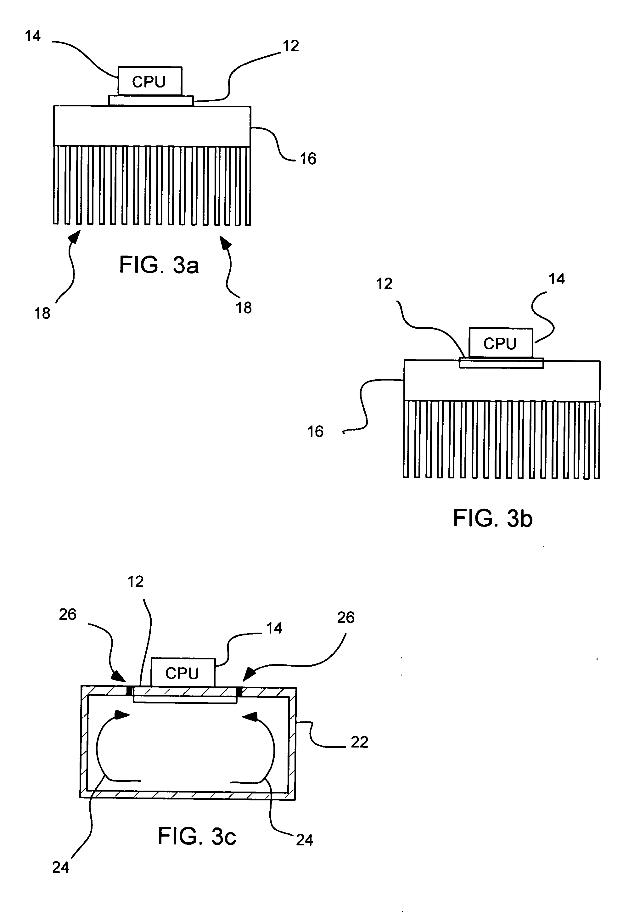
One of the often overlooked challenges is that of heat dissipation.
Most often, this phase of design is neglected or added as a last minute design before the components are produced.
Current methods of heat dissipation, such as by using metal (e.g., Al or Cu) fin radiators, and water evaporation heat pipes, will be inadequate to sufficiently cool future generations of CPUs.
This dramatic change in processing design and architecture is largely the result of an inability to adequately cool CPUs operating at high speeds.
In addition, current technologies are generally not limited by the ability to increase computational speed per se; rather, the difficulty largely lies in the ability to remove heat at a sufficient rate to prevent these chips from burning out.
Thus, most CPUs also include governors which limit the clock speed below what the chip is actually capable of reaching.
However, such materials have a thermal conductivity that is no greater than that of Cu, hence, their ability to dissipate heat from semiconductor chips is limited.
When the chip is heated to above 60° C., the mismatch of thermal expansions between metal and ceramics can create microcracks.
The repeated cycling of temperature tends to aggravate the damage to the chip.
As a result, the performance of the semiconductor will deteriorate.
Moreover, when temperatures reach more than 90° C., the semiconductor portion of the chip may become a conductor so the function of the chip is lost.
In addition, the circuitry may be damaged and the semiconductor is no longer usable (i.e. becomes “burned out”).
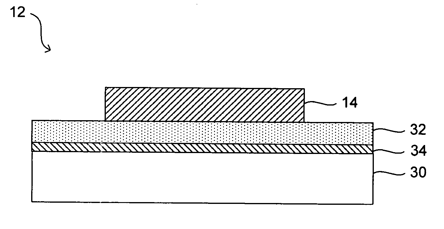
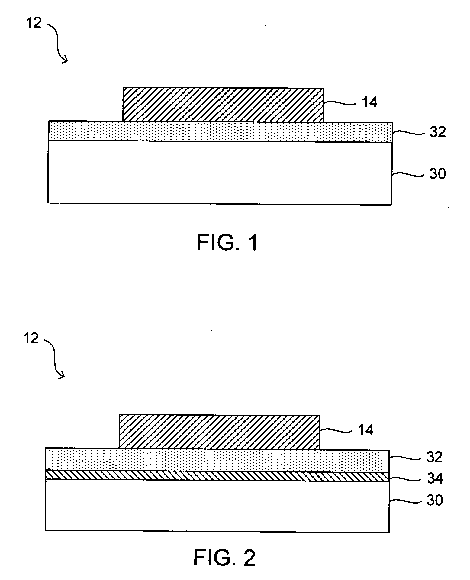
Although heat pipes and heat plates may remove heat very efficiently, the complex vacuum chambers and sophisticated capillary systems prevent designs small enough to dissipate heat directly from a semiconduct

Method used


Image

  • Diamond composite heat spreaders having low thermal mismatch stress and associated methods
  • Diamond composite heat spreaders having low thermal mismatch stress and associated methods
  • Diamond composite heat spreaders having low thermal mismatch stress and associated methods

Examples


Embodiment Construction

[0028] Before the present invention is disclosed and described, it is to be understood that this invention is not limited to the particular structures, process steps, or materials disclosed herein, but is extended to equivalents thereof as would be recognized by those ordinarily skilled in the relevant arts. It should also be understood that terminology employed herein is used for the purpose of describing particular embodiments only and is not intended to be limiting.

[0029] It must be noted that, as used in this specification and the appended claims, the singular forms “a,”“an” and, “the” include plural referents unless the context clearly dictates otherwise. Thus, for example, reference to “a diamond film” includes one or more of such layers, reference to “an intermediate layer” includes reference to one or more of such layers, and reference to “the base” includes reference to one or more of such materials.

[0030] Definitions

[0031] In describing and claiming the present inventio...


PUM

PropertyMeasurementUnit
Temperatureaaaaaaaaaa

Abstract

A diamond composite heat spreader having a low thermal mismatch stress can improve reliability and cost of diamond-based heat spreaders. A diamond composite heat spreader can have a thermally conductive base and a diamond film in thermal contact with the thermally conductive base. The diamond film and the thermally conductive base can have a residual thermal mismatch stress which is less than about 75% of a residual thermal mismatch stress which would result from forming the diamond film on the thermally conductive base using a high temperature deposition process at 700° C. The diamond film can be formed on the thermally conductive base using a low temperature vapor deposition process performed at a temperature from about 10° C to less than 700° C, and typically lower than about 450° C. The diamond films further have high thermal diffusivity and thermal conductivity which allow for dramatic improvements in heat transfer away from a heat source without the need for growing a thick diamond film. By providing a low temperature deposition of the diamond film, residual thermal mismatch stress can be significantly reduced, while allowing for use of well known heat spreaders such as standard copper heat spreaders and associated technologies.

Description

RELATED APPLICATIONS [0001] This application claims the benefit of earlier filed U.S. Provisional Application No. 60 / 681,677, filed May 16, 2005, which is incorporated herein by reference. This application is also a continuation-in-part of U.S. patent application Ser. No. 11 / 056,339, filed Feb. 10, 2005, which is a continuation-in-part of U.S. patent application Ser. No. 10 / 775,543, filed Feb. 9, 2004, which is a continuation-in-part of U.S. patent application Ser. No. 10 / 453,469, filed Jun. 2, 2003 and of U.S. patent application Ser. No. 10 / 270,018, filed Oct. 11, 2002, which are each incorporated by reference herein.FIELD OF THE INVENTION [0002] The present invention relates to diamond composite devices and systems that can be used to conduct or absorb heat away from a heat source. Accordingly, the present invention involves the fields of chemistry, physics, semiconductor technology, and materials science. BACKGROUND OF THE INVENTION [0003] Progress in the semiconductor industry h...

Claims


Application Information

Patent Timeline
IPC IPC(8): H01L31/0312
CPCC23C16/274H01L21/0237H01L21/0245H01L21/02491H01L21/02527H01L21/02595H01L21/0262H01L23/3732H01L2924/09701H01L2924/3011H01L2924/0002H01L2924/00F28F2220/00F28D15/0275F28D15/0233F28D15/0283
Inventor SUNG, CHIEN-MIN
Owner SUNG CHIEN MIN
Why Eureka
Try Eureka