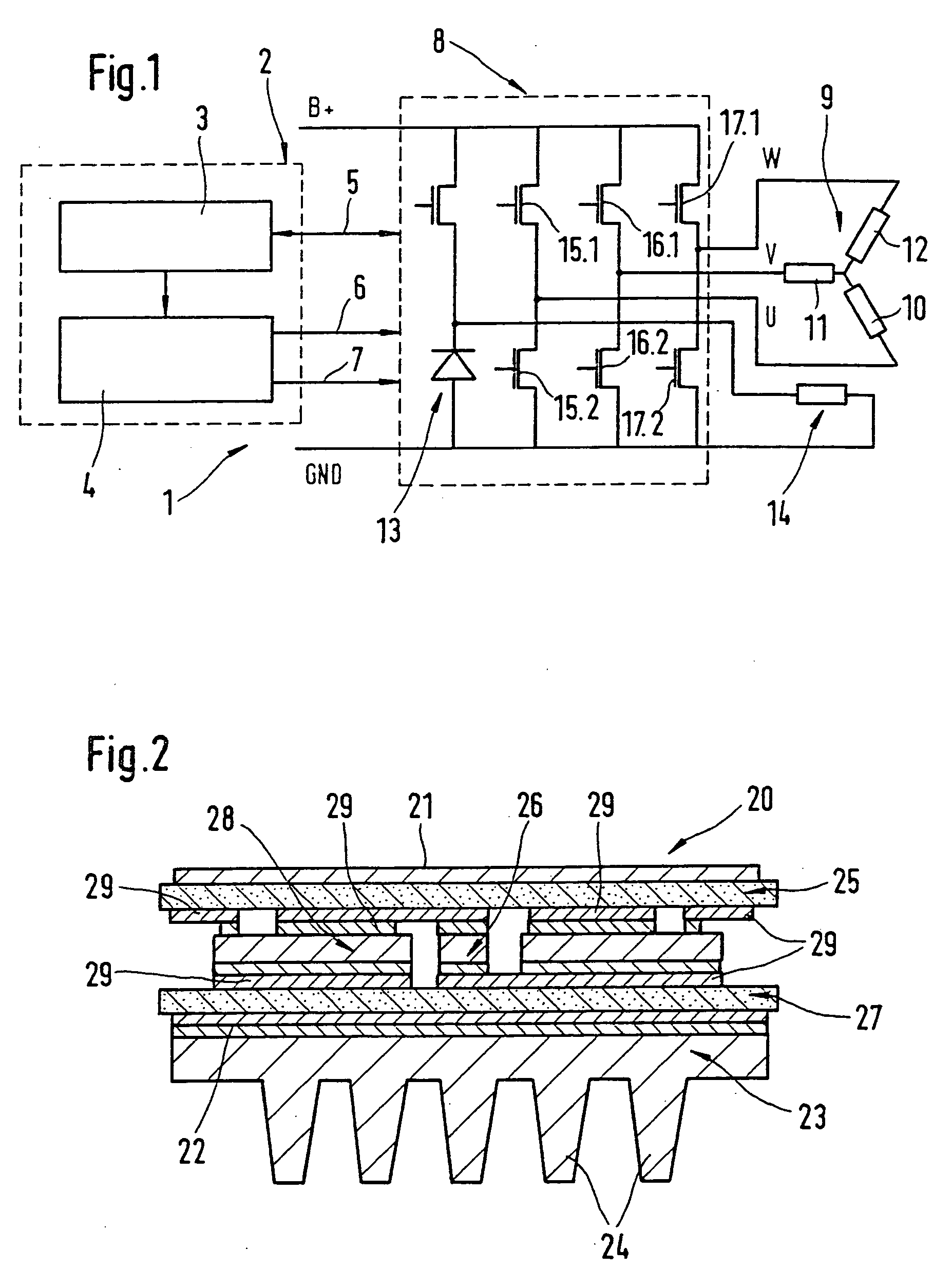
[0006] Through the proposed approach according to the present invention, an active rectifier is provided, which replaces the rectifiers containing the previous passive electronic components. The rectifier proposed according to the present invention containing the active electronic components furthermore has a separation between the power circuit and the control part. The separation of power circuit and control part on the rectifier made of
active components considerably improves the efficiency that is obtained, since power MOS components (
metal oxide semiconductors) are used as active electronic components, with which much higher generator power outputs may be rectified in contrast to passive electronic components such as high-blocking capability diodes. The rectification of higher generator capacities ensures the use of the active rectifier proposed according to the present invention within the 42V vehicle electrical
system that is expected to be used in vehicles in the future, either as the vehicle electrical system or to supplement the previous 12V vehicle electrical system.
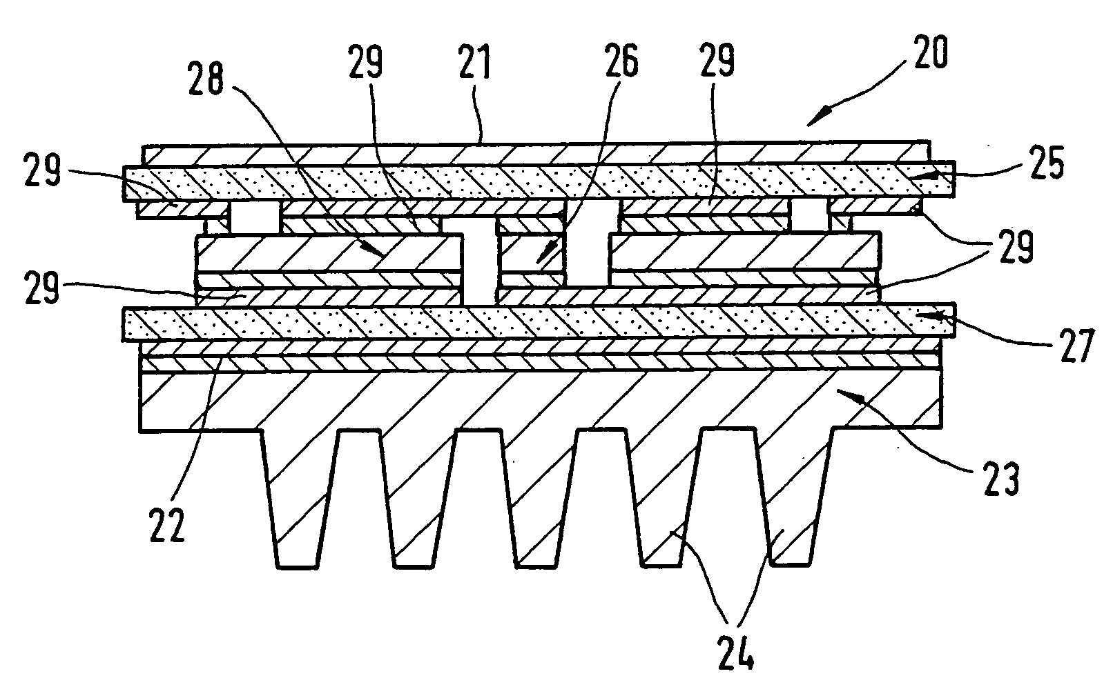
[0007] Since the power components are combined in a power circuit (
power module), and sufficient heat dissipation should be provided here, a cooling device may be provided directly on the power circuit or integrated directly into this power circuit (
power module). With the design according to the present invention of an active rectifier, the
assembly costs are further greatly reduced and lower manufacturing costs per rectifier may be achieved.
[0008] In view of the expected use in the future of 42V vehicle electrical systems, for which there are no cost-effective passive components, such as Zener-diodes, a cost-effective alternative which lowers the
unit cost per rectifier, may be provided by the approach proposed according to the present invention through the use of
active components, such as power MOS components. The use of actively
switching power MOS components is advantageous in that there is less electrical loss since the resistance of actively connected power MOS components is less than that of diodes in forward direction representing high-blocking capability passive components. Due to improved heat dissipation through a
heat sink directly allocated to the power circuit, higher generator output powers that occur in the 42V vehicle electrical system may be rectified. In the event of a sudden load release (load dump), the behavior of the three-phase generator and the vehicle electrical system charge may be influenced favorably compared with the behavior in the case of rectifiers, by actively connecting the power MOS components using passive components and the occurrence of the Zener breakdown on the Z-diodes. The parameter variance of the Zener
voltage caused by the component result in a wide vehicle electrical system
voltage range with respect to the upper limit when a sudden load release (load dump) occurs. By actively connecting the power MOS components, this
voltage range may be reduced with respect to the maximum occurring vehicle electrical system voltage Umax. Furthermore, there is much less tolerance in power MOS components for parameter variance caused by the component.
[0009] With the configuration according to the present invention of a rectifier containing an
active component, the power losses in the rectifier during freewheeling may also be reduced through active connection of the power MOS components. With the proposed design approach, the power-conducting components assigned up to now to the controller, such as for example, field output stages and freewheeling diodes, may also be integrated into the power circuit. This makes it possible to concentrate the altogether necessary cooling effort to dissipate the heat on the power circuit (power module) and to greatly reduce the thermal
power loss on the controller component. A further
advantage is that a simplified
assembly of the controller IC is achieved, in which the integration of the freewheeling
diode and the field output stages into the power circuit (power module) considerably enhances the flexibility with respect to choosing where to
mount the controller IC.
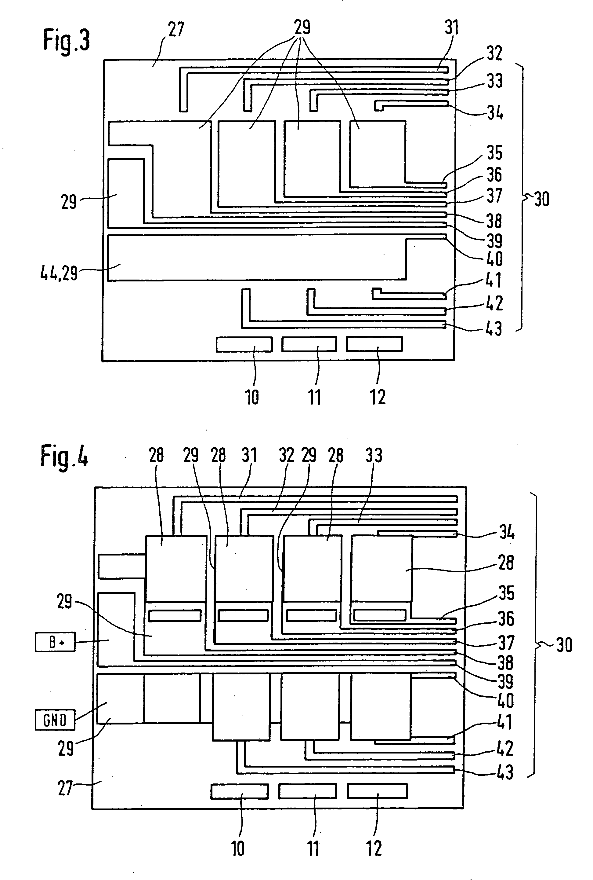
[0010]
Client-specific differences with respect to the plug connections as well as the controller ASIC are limited to the control part (control module), while the power circuit (power module) of the active rectifier is not affected. The power circuit (power module) contains the active rectifier, the field output stage, and the freewheeling
diode and provides an interface for the control part regardless of the
client. The functionality required for controlling the active rectifier proposed according to the present invention, i.e., the
gate driver, may be mounted in the controller ASIC in a single-
chip approach. If the entire power circuit (power module) is designed such that it is soldered on both sides, production costs may be kept low since
assembly lines with
reflow soldering equipment or vacuum through-type furnaces may be used to manufacture these contacts and allow
industrial scale manufacture, resulting in a lower
unit cost per active rectifier according to the approach according to the present invention. An improved thermal connection may be established through
soldering point contacts on both sides. Through the plastic
extrusion coating method (molding), the
active components, i.e., power MOS components, may be effectively protected from outside influences, such as splashed water, shaking and
dirt accumulation, and at the same time offer level assembly surfaces for
power circuits and control parts of the active rectifier which are stack-mounted, for example.

