Vacuum thermal insulation material and equipment using the same

a technology of thermal applied in the field of vacuum heat insulation material and equipment, can solve the problems that the structure of these conventional techniques cannot address these problems sufficiently, and achieve the effect of improving heat insulation performan

Inactive Publication Date: 2006-07-20
PANASONIC CORP
View PDF7 Cites 15 Cited by
  • Summary
  • Abstract
  • Description
  • Claims
  • Application Information

AI Technical Summary

Benefits of technology

[0008] A vacuum heat insulator of the present invention includes a core, an enveloping member covering the core, and a radiation heat transfer suppressor disposed on the surface of the enveloping member on a high temperature side thereof. The inside of the enveloping member is evacuated. This structure prevents infrared ray in the vacuum heat insulator to be absorbed and suppresses radiation heat transferred to the surface of the enveloping member. Thus, heat-insulating performance is improved. The radiation heat transfer suppressor can be provided away from the surface of the enveloping member.

Problems solved by technology

The structures of these conventional techniques cannot address these problems sufficiently.

Method used


Image

  • Vacuum thermal insulation material and equipment using the same
  • Vacuum thermal insulation material and equipment using the same
  • Vacuum thermal insulation material and equipment using the same

Examples


first exemplary embodiment

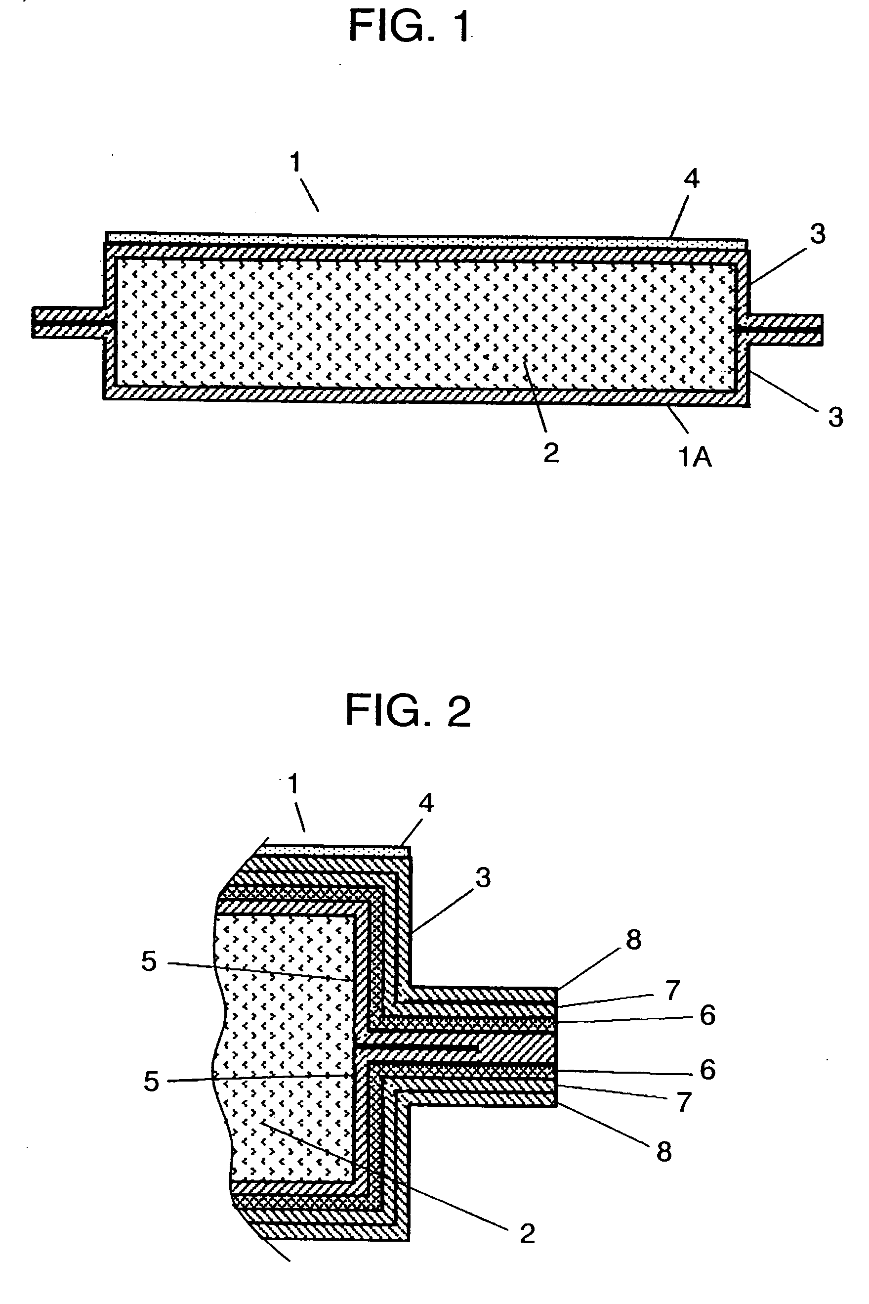
[0026] First, a description is provided of a case in which a coating including an infrared reflectance component is formed as radiation heat transfer suppressor 4. For samples 1 through 4, various kinds of coatings are formed on the surface of enveloping member 3 of vacuum heat insulator body 1A as radiation heat transfer suppressor 4. The heat-insulating performance of vacuum heat insulator 1 is evaluated by measuring the surface temperature on the low-temperature side when a heat at 150° C. is applied to the surface on the high-temperature side.

[0027] Formed in sample 1 is a coating containing leafing aluminum flake pigment, i.e. a metal powder, as an infrared reflectance component and epoxy resin as a resin component. Formed in sample 2 is a coating containing leafing aluminum flake pigment, similar to sample 1, and polychlorotrifluoroethylene, i.e. a fluorocarbon resin, as a resin component. Formed in sample 3 is a coating containing silicon nitride, i.e. an inorganic powder, a...

second exemplary embodiment

[0038] Next, a description is provided of radiation heat transfer suppressor 4 formed of a laminate of inorganic material films having different reflectances. The basic structure of the vacuum heat insulator is similar to those of FIGS. 1 and 2 in accordance with the first exemplary embodiment.

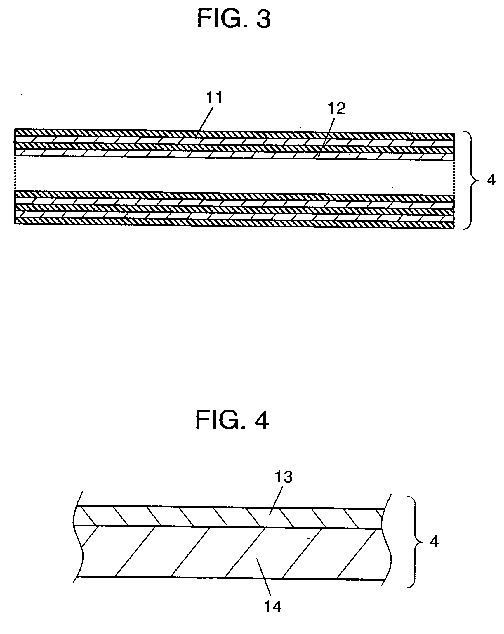
[0039]FIG. 3 is a sectional view of radiation heat transfer suppressor 4 in accordance with this embodiment. Radiation heat conduction suppressor 4 of this embodiment is a radiation heat suppressing film in which first inorganic film 11 made of magnesium fluoride and second inorganic film 12 made of calcium fluoride and having a different reflectance are alternately laminated in four layers.

[0040] When inorganic material films having different reflectances are alternately laminated in a thickness of the quarter of a specific wavelength, fronts of the waves reflected from the boundary surfaces of respective layers overlap additively. This allows the wavelength of far infrared rays to selectiv...

third exemplary embodiment

[0046] Next, a description is provided of a case in which radiation heat transfer suppressor 4 is formed of a metal film. The basic structure of the vacuum heat insulator is similar to those of FIGS. 1 and 2 in accordance with the first exemplary embodiment.

[0047] In this embodiment, a metal film forming radiation heat transfer suppressor 4 is made of a metal foil or laminating them. Alternatively, as shown in the sectional view of FIG. 4, the metal film can be made of a thin layer of metal film 13 formed by deposition, sputtering, or electrode position method, or a laminate thereof. The metal film can also be made by laminating a metal film with thin layers of inorganic materials or semiconductors.

[0048]FIG. 5 is a characteristics diagram showing a relation between black body emissivity and wavelengths at 150° C. FIG. 6 is a characteristics diagram showing reflectance when light is perpendicularly incident on a silver (Ag)-deposited surface.

[0049] When a heat at 150° C. is appli...


PUM

PropertyMeasurementUnit
melting pointaaaaaaaaaa
melting pointsaaaaaaaaaa
temperatureaaaaaaaaaa

Abstract

A radiation heat transfer suppressor for inhibiting heat transfer by infrared rays is provided on the external surface of the enveloping member of a vacuum heat insulator. In heat-blocking or keep warm using a vacuum heat insulator, a surface having a radiation heat transfer suppressor is faced to a high-temperature side. Thus, the vacuum heat insulator exhibits excellent heat-insulating performance in a temperature range of 150° C. or higher.

Description

[0001] This application is a U.S. National Phase Application of PCT International Application PCT / JP2004 / 009295.TECHNICAL FIELD [0002] The present invention relates to a vacuum heat insulator and apparatuses using the vacuum heat insulator. It particularly relates to heat insulation and keep warm in apparatuses having high-temperature portions, including printing machines such as a copying machine and laser printer, electronic equipment such as a computer, and further a water heater. BACKGROUND ART [0003] Energy saving has recently been desired because of the importance of preventing global warming, one of concerns over global environment. In every field, energy saving is promoted. Required for general equipment using heat or cold and members related to houses is a heat-insulating member having excellent heat-insulating performance in low—or medium-temperature areas ranging from −30 to 150° C., from the viewpoint of efficient use of heat. On the other hand, business equipment, such ...

Claims


Application Information

Patent Timeline
Patent Type & Authority Applications(United States)
IPC IPC(8): F24H1/18F16L59/065
CPCF16L59/065Y10T428/1352Y10T428/13F16L59/08
Inventor YUASA, AKIKOKOJIMA, SHINYA
Owner PANASONIC CORP
Why Eureka
Try Eureka