
Image forming method using photothermographic material

Inactive Publication Date: 2006-07-20
FUJIFILM CORP
View PDF4 Cites 1 Cited by
  • Summary
  • Abstract
  • Description
  • Claims
  • Application Information

AI Technical Summary

Benefits of technology

[0365] The method of mixing the silver halide and the organic silver salt can include a method of mixing a separately prepared photosensitive silver halide and an organic silver salt by a high speed stirrer, ball mill, sand mill, colloid mill, vibration mill, homogenizer, or the like, or a method of mixing a photosensitive silver halide completed for preparation at any timing in the preparation of an organic silver salt and preparing the organic silver salt. The effect of the invention can be obtained preferably by any of the methods described above.

Problems solved by technology

While various kinds of hard copy systems using pigments or dyes, such as ink-jet printers or electrophotographic systems, have been distributed as general image forming systems using such digital imaging recording materials, images on the digital imaging recording materials obtained by such general image forming systems are insufficient in terms of the image quality (sharpness, granularity, gradation, and tone) needed for medical images used in making diagnoses, and high recording speeds (sensitivity).
These kinds of digital imaging recording materials have not reached a level at which they can replace medical silver halide film processed with conventional wet development.
However, on the other hand, there are many problems such as storage stability of the photothermographic material and image storage stability.
Many efforts to improve the above defects have been carried out from various standpoints, but are still insufficient.
However, there are conventionally no descriptions about a thermal developing apparatus for these double-sided coated photothermographic materials.
The reasons are because, as mentioned above, the sensitivity of silver iodide is low and there are no effective sensitizing means therefor, and further, because technical barriers become even higher in thermal development.

Method used


Image

  • Image forming method using photothermographic material
  • Image forming method using photothermographic material
  • Image forming method using photothermographic material

Examples


example 1

1. Preparation of PET Support and Undercoating

1-1. Film Manufacturing

[0645] PET having IV (intrinsic viscosity) of 0.66 (measured in phenol / tetrachloroethane=6 / 4 (mass ratio) at 25° C.) was obtained according to a conventional manner using terephthalic acid and ethylene glycol. The product was pelletized, dried at 130° C. for 4 hours, and colored blue with the blue dye (1,4-bis(2,6-diethylanilinoanthraquinone). Thereafter, the mixture was extruded from a T-die and rapidly cooled to form a non-tentered film.

[0646] The film was stretched along the longitudinal direction by 3.3 times using rollers of different peripheral speeds, and then stretched along the transverse direction by 4.5 times using a tenter machine. The temperatures used for these operations were 110° C. and 130° C., respectively. Then, the film was subjected to thermal fixation at 240° C. for 20 seconds, and relaxed by 4% along the transverse direction at the same temperature. Thereafter, the chucking part was slit...

example 2

1. Preparation of Fluorescent Intensifying Screen A

[0763] 1) Preparation of Undercoat Layer

[0764] A light reflecting layer comprising alumina powder was coated on a polyethylene terephthalate film (support) having a thickness of 250 μm in a similar manner to Example 4 in JP-A. No. 2001-124898. The light reflecting layer, which had a film thickness of 50 μm after drying, was prepared.

[0765] 2) Preparation of Fluorescent Substance Sheet

[0766] 250 g of BaFBr:Eu fluorescent substance (mean particle size of 3.5 μm), 8 g of polyurethane type binder resin (manufactured by Dai Nippon Ink & Chemicals, Inc., trade name: PANDEX T5265M), 2 g of epoxy type binder resin (manufactured by Yuka Shell Epoxy Co., Ltd., trade name: EPIKOTE 1001) and 0.5 g of isocyanate compounds (manufactured by Nippon Polyurethane Industry Co., Ltd., trade name: CORONATE HX) were added into methylethylketone, and the mixture was then dispersed by a propeller mixer to prepare the coating solution for the fluoresce...

example 3

[0775] A silver halide emulsion prepared similar to the silver halide emulsion B of Example 1 was kept at 38° C. with stirring, and thereto was added 5 mL of a 0.34% by weight methanol solution of 1,2-benzisothiazoline-3-one, and after 20 minutes the temperature was elevated to 45° C. At 20 minutes after elevating the temperature, sodium benzene thiosulfonate in a methanol solution was added at 7.6×10⁻⁵ mol per 1 mol of silver. At additional 5 minutes later, sulfur sensitizer 4-oxo-3-benzyl-oxazolidine-2-thione in a methanol solution was added at 4.5×10⁻⁵ mol per 1 mol of silver and further, after 10 minutes, chloroauric acid in an aqueous solution at 8×10⁻⁶ mol per 1 mol of silver and potassium thiocyanate in an aqueous solution at 8×10⁻³ mol per 1 mol of silver were added, and subjected to ripening for 60 minutes.

[0776] And then, 1.3 mL of a 0.8% by weight N,N′-dihydroxy-N″,N″-diethylmelamine in methanol solution was added thereto, and at additional 4 minutes thereafter, 5-methyl...


PUM


Abstract

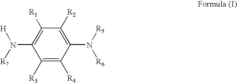
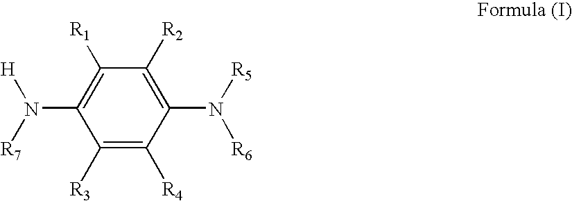
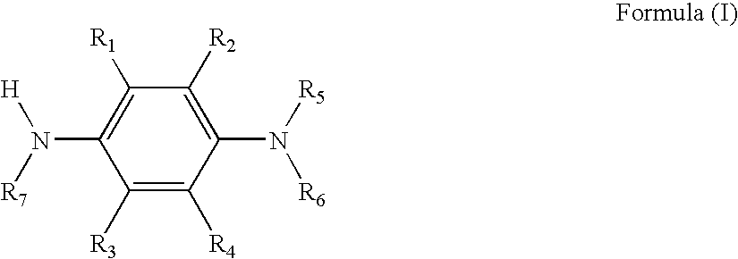
The invention provides an image forming method for forming an image using a photothermographic material having an image forming layer on both sides of a support, wherein the image forming layer contains at least a photosensitive silver halide, an organic silver salt, a reducing agent for silver ions represented by the following formula (I), a coupler, and a binder: wherein R1, R2, R3, and R4 each independently represent a hydrogen atom or a substituent; R5 and R6 each independently represent an alkyl group, an aryl group, a heterocyclic group, an acyl group, or a sulfonyl group; R7 represents R11—O—CO—, R12—CO—CO—, R13—NH—CO—, R14—SO2—, R15—W—C(R16)(R17)(R18)—, R19—SO2NHCO—, R20—CONHCO—, R21—SO2NHSO2—, R22—CONHSO2— or (M)1 / nOSO2—; and M represents a cation having a valency of n. An image forming method using a photothermographic material which exhibits low fog and excellent storage stability is provided.

Description

CROSS-REFERENCE TO RELATED APPLICATION [0001] This application claims priority under 35 USC 119 from Japanese Patent Application Nos. 2005-010544 and 2005-043177, the disclosures of which are incorporated by reference herein. BACKGROUND OF THE INVENTION [0002] 1. Field of the Invention [0003] The present invention relates to an image forming method using a photothermographic material preferably used in the field of films for medical diagnosis. More particularly, the invention relates to an image forming method using a photothermographic material which exhibits low fog and excellent storage stability. [0004] 2. Description of the Related Art [0005] In recent years, in the medical field and the graphic arts field, there has been a strong desire for providing a dry photographic process from the viewpoints of protecting the environment and economy of space. Further, the development of digitization in these fields has resulted in the rapid development of systems in which image informatio...

Claims


Application Information

Patent Timeline
IPC IPC(8): G03C5/16
CPCG03C1/49818G03C1/49827G03C1/49854G03C1/49881G03C7/32G03C2001/03558G03C1/0051G03C2001/7425G03C2005/168
Inventor YOSHIOKA, YASUHIROMIFUNE, HIROYUKI
Owner FUJIFILM CORP
Learn More