Fuel cell system

a fuel cell and system technology, applied in the field of fuel cells, can solve problems such as thermodynamics and/or kinetics, and achieve the effect of improving thermal conductivity across the stack and alleviating excessive cooling

Inactive Publication Date: 2006-07-27
CHAOZHOU THREE CIRCLE GRP
View PDF3 Cites 16 Cited by
  • Summary
  • Abstract
  • Description
  • Claims
  • Application Information

AI Technical Summary

Benefits of technology

[0045] The preferred relatively high levels of methane in the fuel stream to the fuel cell anode have the potential to cause excessive cooling of the fuel cell as a result of the endothermic methane internal steam reforming reaction. This problem is more likely to be encountered in a wholly ceramic SOFC fuel cell stack due to the low thermal conductivity of ceramic materials, but ca

Problems solved by technology

Such thermodynamic and/or kinetic limitations may even convert some or all of the methane

Method used


Image

  • Fuel cell system
  • Fuel cell system
  • Fuel cell system

Examples


example 1

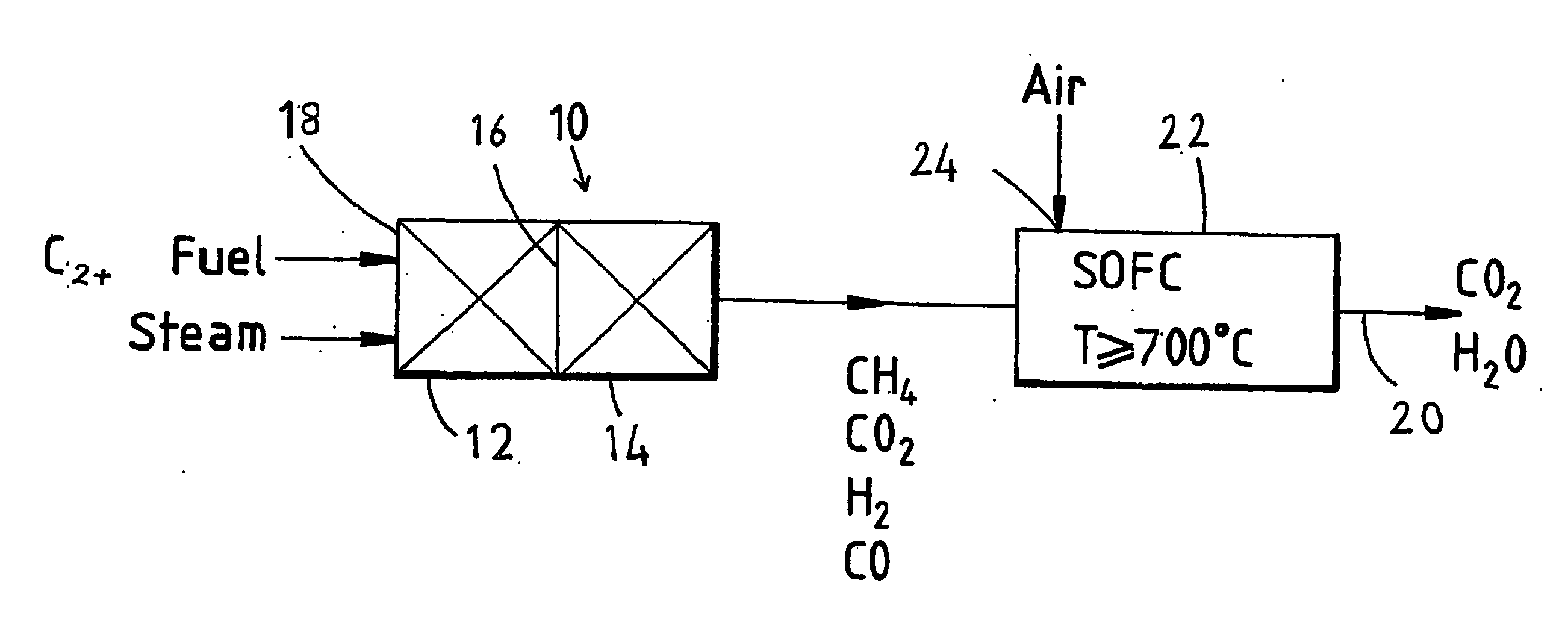
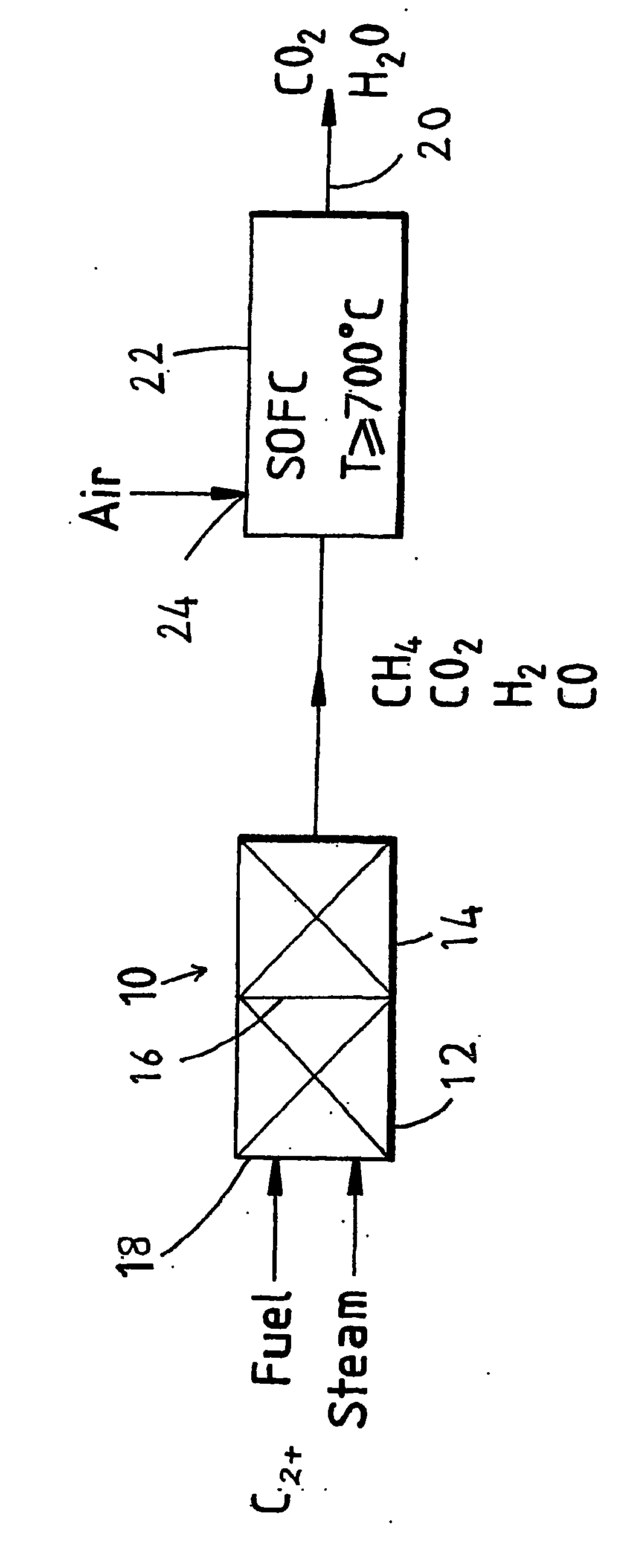
[0054] Case 1: A single-stage reformer operated at 400° C. [0055] Case 2: A two-stage reformer with the first stage operated at 450° C. and the second stage at 350° C.

A pure propane feed with a steam-to-carbon ratio of 1.5 is used in these calculations.

[0056] The results are as follows:

Case 1:Methane:56.45%(v / v)Hydrogen:24.71Carbon Dioxide:18.34Carbon Monoxide:0.50Case 2Methane:66.48%(v / v)Hydrogen:15.52Carbon Dioxide:17.86Carbon Monoxide:0.14

[0057] It may be seen that the resultant fuel stream methane content is higher in Case 2. In principle the methane content for Case 1 can be increased by operating at the lower temperature of 350° C. However, in practice most commercial catalysts will not have sufficiently high activity for full conversion of higher hydrocarbons at such low temperatures. Similarly, the temperature of the second stage of Case 2 can be lowered to 300° C. for higher methane content. Again, similar practical restrictions apply. From these considerations the abo...

example 2

[0058] Case 1: A single-stage reformer operated at 380° C. [0059] Case 2: A two-stage reformer with the first stage operated at 380° C. and the second stage at 334° C.

[0060] A pure propane feed with a steam-to-carbon ratio of 1.5 is used in these calculations.

[0061] The results are as follows:

Case 1:Methane:61.84%(v / v)Hydrogen:22.45Carbon Dioxide:15.43Carbon Monoxide:0.28Case 2:Methane:71.4%(v / v)Hydrogen:14.1Carbon Dioxide:14.4Carbon Monoxide:0.1

Experimental Work

example 3

[0062] Example 2 was experimented in a dual-bed microreactor. In the first experiment, the first bed was loaded with 1 g of the catalyst C11-PR, a commercial pre-reforming catalyst obtained from United Catalysts Inc. The experiment was performed with the first bed maintained at 380° C. and with no catalyst placed in the second bed. The experiment was therefore a comparative example in accordance with Case 1 of Example 2 and with the process of PCT / AU00 / 00974. The experiment was performed over a period of 100 hours. Steam-to-Carbon ratio was 1.5 and the space velocity of the reactant was 1250 h−1. The results are as follows:

TABLE 1Propane pre-reforming in a single-bed microreactorHours OnGas CompositionSelectivityStreamC3H8CO2H2CH4CH4 / H2 2.2013.625.860.52.35 4.8013.725.360.82.4 7.3013.626.260.02.2925.3013.923.8261.62.5927.8013.924.861.22.4730.3013.825.360.72.496.8013.825.560.52.3799.3013.726.259.92.29101.8 013.726.359.82.28102.8 013.726.559.72.25Average013.725.660.52.37


PUM


Abstract

A process for producing electricity in a fuel cell which comprises: a) pre-reforming a higher carbon (C2+) hydro-carbon fuel in a pre-reformer under conditions effective to achieve substantially complete conversion of higher carbon (C2+) hydro-carbons to produce a pre-reformed fuel stream; b) subjecting the pre-reformed fuel stream to methanation under conditions effective to produce a fuel stream having an increased concentration of methane relative to the pre-reformed fuel stream; and c) supplying the fuel stream and an oxidant to a high temperature fuel cell in which methane is reformed and electricity is produced by reacting the fuel stream at an anode of the fuel cell and reacting the oxidant at a cathode of the fuel cell.

Description

TECHNICAL FIELD [0001] The present invention relates to fuel cells and is particularly concerned with the fuel supply to a fuel cell electrical power generating system. BACKGROUND ART [0002] Fuel cells convert gaseous fuels (such as hydrogen, natural gas and gasified coal) via an electrochemical process directly into electricity. A fuel cell continuously produces power when supplied with fuel and oxidant, normally air. A typical fuel cell consists of an electrolyte (ionic conductor, H+, O2−, CO32− etc.) in contact with two electrodes (mainly electronic conductors). On shorting the cell through an external load, fuel oxidises at the anode resulting in the release of electrons which flow through the external load and reduce oxygen at the cathode. The charge flow in the external circuit is balanced by ionic current flows within the electrolyte. Thus, at the cathode oxygen from the air or other oxidant is dissociated and converted to oxygen ions which migrate through the electrolyte mem...

Claims


Application Information

Patent Timeline
IPC IPC(8): H01M8/06H01M8/0612
CPCH01M8/0612Y02E60/50
Inventor AHMED, KHALIG
Owner CHAOZHOU THREE CIRCLE GRP
Why Eureka
Try Eureka