Mass spectrometer

a mass spectrometer and mass spectrometer technology, applied in the field of mass spectrometers, can solve the problems of low utilization efficiency, low utilization efficiency of ion, and high speed acquisition of high quality spectra that meets industrial applications, and achieves the effects of speeding up amino acid sequence analysis, speeding up spectral acquisition, and facilitating combination with cid

Active Publication Date: 2006-08-03
HITACHI HIGH-TECH CORP
View PDF9 Cites 49 Cited by
  • Summary
  • Abstract
  • Description
  • Claims
  • Application Information

AI Technical Summary

Benefits of technology

[0043] According to the present invention, speedup of spectral acquisition is achieved by ECD reaction unit using an RF ion trap and its combination with CID is made easy. As the res

Problems solved by technology

Although experimental research has been reported for the ECD reaction using an RF electric field and magnetic field, high speed acquisition of high quality spectra excellent in S/N that meets industrial application has not been realized with the use of either system that employs the three dimensional ion trap or the linear ion trap.
For high speed acquisition of spectra, there are two problems that are speed-up of the ECD reaction and enhancement of ion utilization efficiency.
On the other hand, the efficiency of ion utilization is low because the efficiency of ion inje

Method used


Image

  • Mass spectrometer
  • Mass spectrometer
  • Mass spectrometer

Examples


first embodiment

of Mass Spectrometer Provided with ECD Reaction Unit

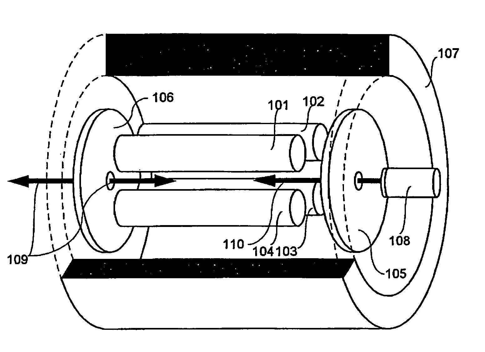
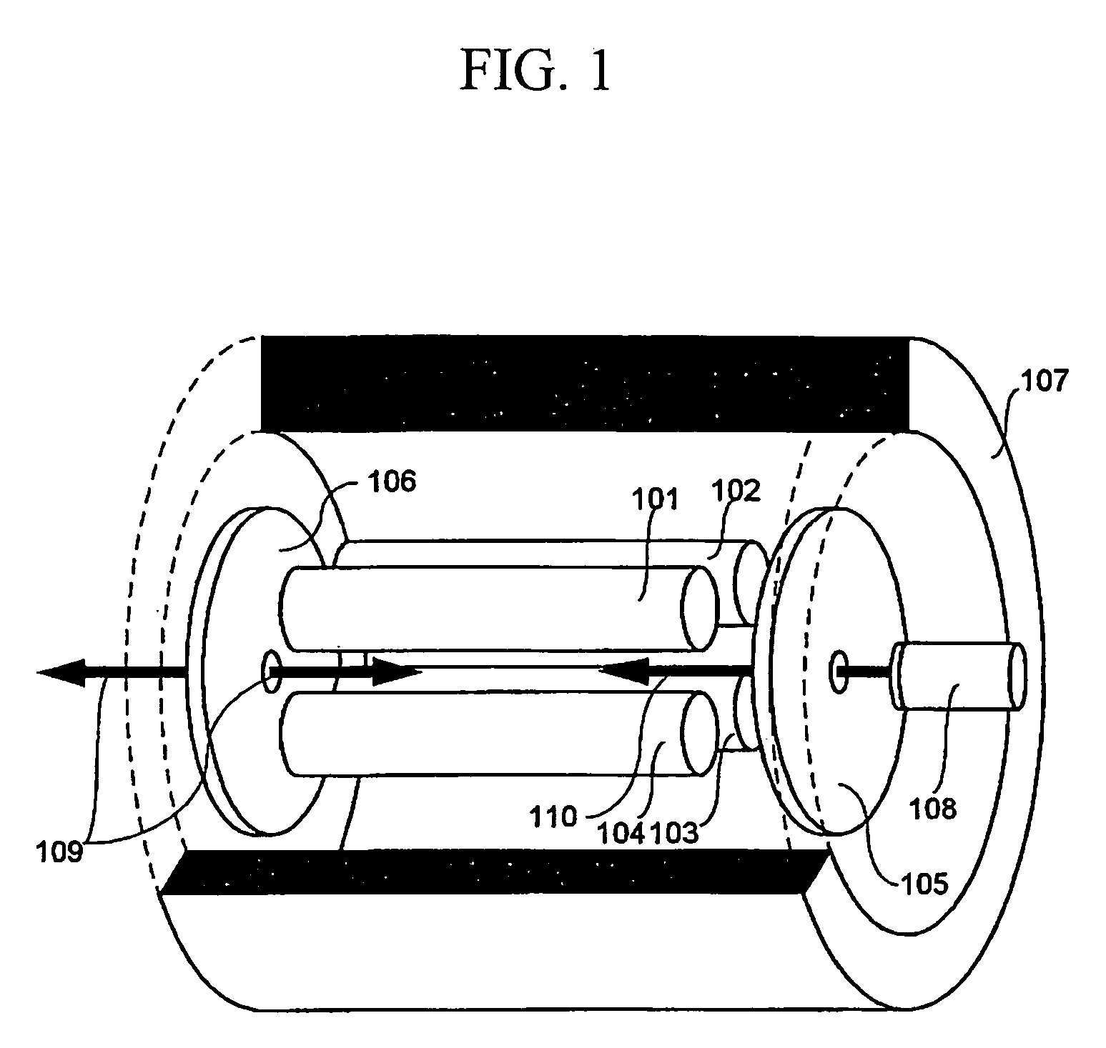
[0095]FIG. 10 is a schematic diagram to explain an example of a mass spectrometer in which an ECD cell provided with a magnetic field-generating unit using a solenoid is employed for ECD and CID and this reaction cell is employed for mass analysis. It is a feature that an ion source is provided to one ion inlet of a quadrupole deflector and an ion detector is provided to the other inlet.

[0096] The ECD and CID reaction unit includes the electrodes 101 to 104 forming linear multipole electrodes, an RF power source 1027 to apply an ion trap RF thereto, the AC power source 913 to resonate ions, the wall electrodes 105 and 106, the solenoid coil 802 and the driving current source thereof 912, an electron source 1008 formed of a filament, the helium gas inlet pipe 911, and the quadrupole deflector 409 to 412. In addition to the present ECD and CID unit, a mass spectrometer is formed by further including an ESI ion source composed of a c...

second embodiment

of Mass Spectrometer Provided with ECD Reaction Unit

[0105]FIG. 11 is a schematic diagram of an example to explain a mass spectrometer in which the ECD cell provided with the magnetic field-generating unit using the solenoid is employed for ECD, and a linear ion trap mass analysis unit and a TOF mass analysis unit are provided. It is a feature that, in addition to the ECD-CID reaction unit having a structure in which the solenoid is a magnetic field-generating means and the quadrupole deflector is provided, the ion source and the linear ion trap mass analysis unit are provided at one ion port of the quadrupole deflector and another mass analysis unit is provided at the other port. For the mass analysis unit, the TOF mass analysis unit with high mass resolution is employed. It is also a feature that molecular identification capability of the present embodiment becomes higher compared with the first embodiment due to high mass resolution of an obtained spectrum. In the present embodime...

third embodiment

of Mass spectrometer Provided with ECD Reaction Unit

[0118]FIG. 12 is a schematic diagram to explain an embodiment of a mass spectrometer provided with an ECD reaction unit with the use of an ECD cell provided with the magnetic field-generating unit using a permanent magnet, the linear ion trap mass analysis unit, and the TOF mass analysis unit. It is a feature that, in addition to the ECD reaction unit having a structure in which the permanent magnet is a magnetic field-generating means and the quadrupole deflector is provided, the ion source and the linear ion trap mass analysis unit are provided at one ion port of the quadrupole deflector and another mass analysis unit is provided at the other port. It is also a feature that a low-cost and simple analyzer structure is provided by employing the permanent magnet. Since control of the magnetic field is not possible, it is difficult to perform CID in the ECD reaction unit. However, it is possible to perform CID by the linear ion trap ...


PUM


Abstract

An electron capture dissociation device to implement a combination of electron capture dissociation and collision dissociation and a mass spectrometer with the use thereof are provided. This device includes a linear ion trap provided with linear multipole electrodes applied with a radio frequency electric field and wall electrodes that are arranged on both ends in the axis direction of the linear multipole electrodes, have holes on the central axis thereof, and generate a wall electric field by being applied with a direct-current voltage, a cylindrical magnetic field-generating unit that generates a magnetic field parallel to the central axis of the linear multipole electrodes and surrounds the linear ion trap, and an electron source arranged opposite to the linear multipole electrodes with sandwiching one of the wall electrodes. The electron generation site of the electron source is placed in the inside of the magnetic field generated by the magnetic field-generating unit.

Description

CLAIM OF PRIORITY [0001] The present application claims priority from Japanese application JP 2005-020543 filed on Jan. 28, 2005 and JP 2005-160861 filed on Jun. 1, 2005, the contents of which are hereby incorporated by reference into this application. FIELD OF THE INVENTION [0002] The present invention relates to a method and an apparatus for analysis of sequence structure of large biomolecules with the use of mass spectrometry. BACKGROUND OF THE INVENTION [0003] After completion of the analysis of the human DNA sequence, currently the structural analysis of proteins synthesized from this genetic information as well as post-translationally modified molecules from these proteins has become increasingly important. As a method of the structural analysis, i.e. amino-acids sequence analysis, mass spectrometers are available. Particularly, mass spectrometers composed of ion traps and Q mass filters using a radio frequency (RF) electric field and time-of-flight (TOF) mass spectrometers ar...

Claims


Application Information

Patent Timeline
IPC IPC(8): B01D59/44H01J49/00
CPCH01J49/005H01J49/0054H01J49/4225
Inventor BABA, TAKASHISATAKE, HIROYUKIWAKI, IZUMI
Owner HITACHI HIGH-TECH CORP
Why Eureka
Try Eureka