Apparatus and process for carbon nanotube growth

Inactive Publication Date: 2006-08-24
MOTOROLA INC
View PDF10 Cites 61 Cited by
  • Summary
  • Abstract
  • Description
  • Claims
  • Application Information

AI Technical Summary

Benefits of technology

[0040] Referring to FIG. 10, an intermediate electrode 81 having an alternating current or radio frequency signal 82 applied provides a means for imparting additional energy to the process to create additional disassociation of the gas with the subsequent creation of additional species. During the catalyst induction/or carbon nanotube 26 growth step, the HF CVD reactor could run in this hybrid configuration. First, an additional AC or RF bias voltage 82 is applied between the hot heating element 16 and a plasma-grid placed underneath in the space between the heating element 16 and the substrate 13. Second, a DC or low frequency RF substrate bias 25 could be applied to the substrate 13 to impact its surface with electrons. The function of the AC or RF bias 82 is to generate conventional plasma between the heating element 16 and the intermediate grid 81 leading to gas process dissociation and activation enhancement in this filament-grid confined region. The function of the grid 81 and the DC bias 25 is to shield the effect of ion bombardment at the substrate 13 and to accelerate only the electrons and the reactive hydrocarbon radicals towards the substrate 13. Independent control of the different voltages with respect to the heating element 16 temperature, permits a fine tuning of the gas dissociation and electrons flowing to the substrate 13. In this hybrid mode arrangement, the HF-CVD reactor exhibits higher process flexibility and capability.
[0041] Referring to FIG. 11, an alternating current or radio frequency signal is applied to the heating element 16 and gas showerhead 14, or in absence of showerhead to a thermal shield located over the heating element 16. This arrangement results in additional energy imparted to the precursor gas, causing more efficient disassociation of the gas species. A DC substrate bias is applied to the substrate 13 to extract the saturated electron from the heating element 16 and increase the electron impact of its surface. Both hybrid configuration of HF-CVD allow for independently control of the catalyst induction and carbon nanotube growth stages, to carry out homogenous and uniform carbon nonotube 26 growth, to enhance the substrate 13 bombardment by electrons and shift down the temperature to the range where only selective carbon nanotube 26 growth is still the dominant process. These hybrid HF CVD techniques in comparison to the standard HF CVD technique show significant advantage to control the carbon nanotube 26 growth kinetics over a broader range of substrate 13 materials.
[0042] Referring to FIG. 12, yet another embodiment comprises

Problems solved by technology

Unfortunately, these methods typically yield bulk materials with tangled nanotubes.
Arc-discharge and laser techniques do not provide the high purity and limited defectivity that may be obtained by the CVD process.
The arc-discharge and laser ablation techniques are not direct growth methods, but require purification, placement and post treatment of the grown carbon nanotube.
The formation of carbides is known to promote filament fragility and consequently filament lifetime issues.
Furthermore, the filament brittleness outcome is intensified by the hydrogen that is present in the process gas mixture.
As a result, the hot and thin filaments tend to physically sag toward the substrate due to gravity; thereby producing deformed filaments and uneven filament grid gap over the planar substrate surface.
As the substrate to filament distance is thus distorted by this filament sagging, the non regular shape of the hot filament grid promotes localized temperature variation and consequently growth non uniformity over large substrate area.
However, integration of carbon nanotube fie

Method used


Image

  • Apparatus and process for carbon nanotube growth
  • Apparatus and process for carbon nanotube growth
  • Apparatus and process for carbon nanotube growth

Examples


process example

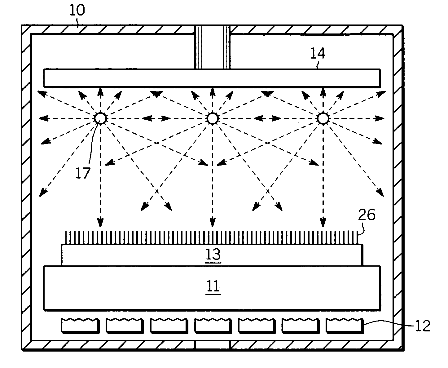
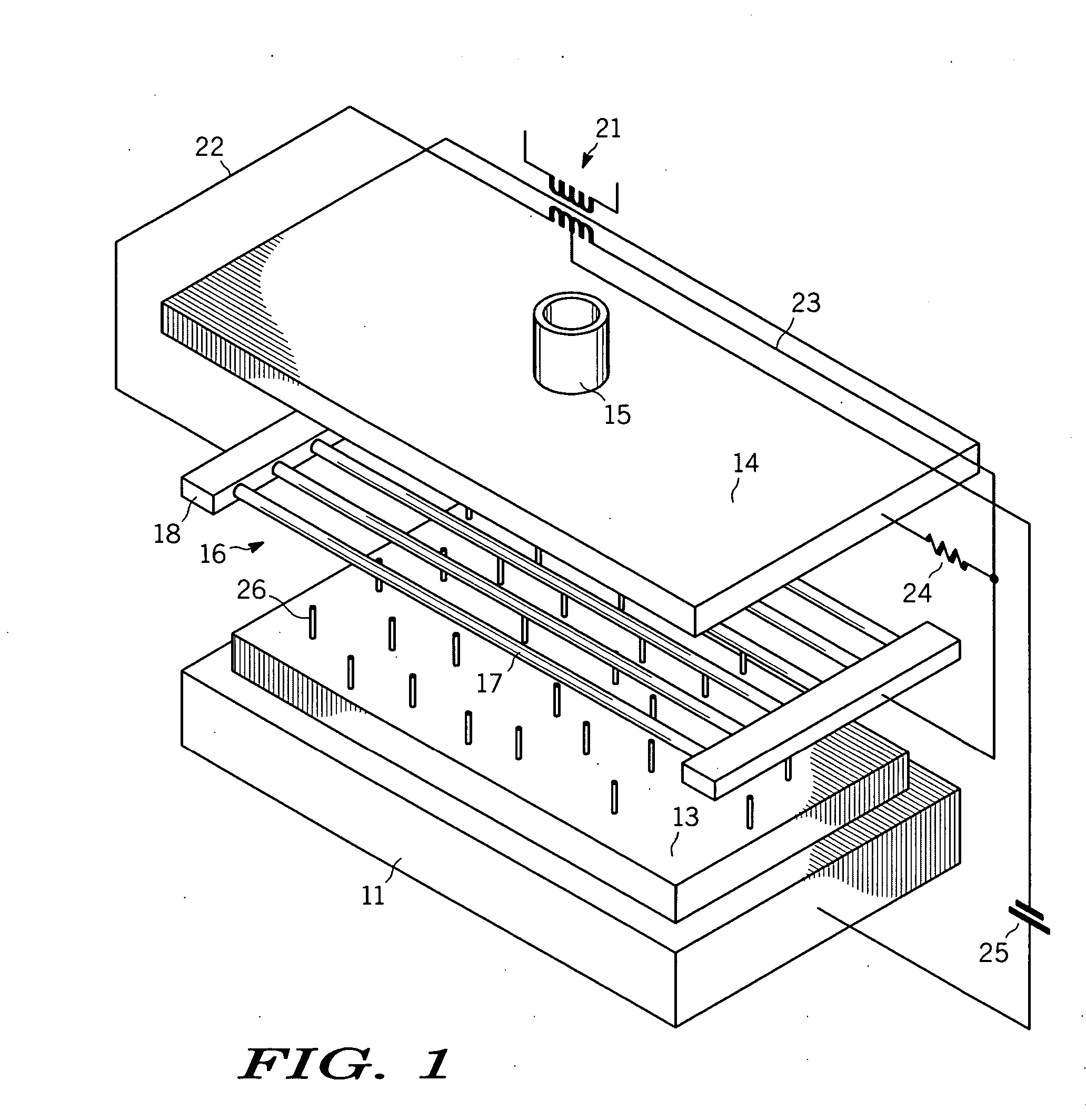
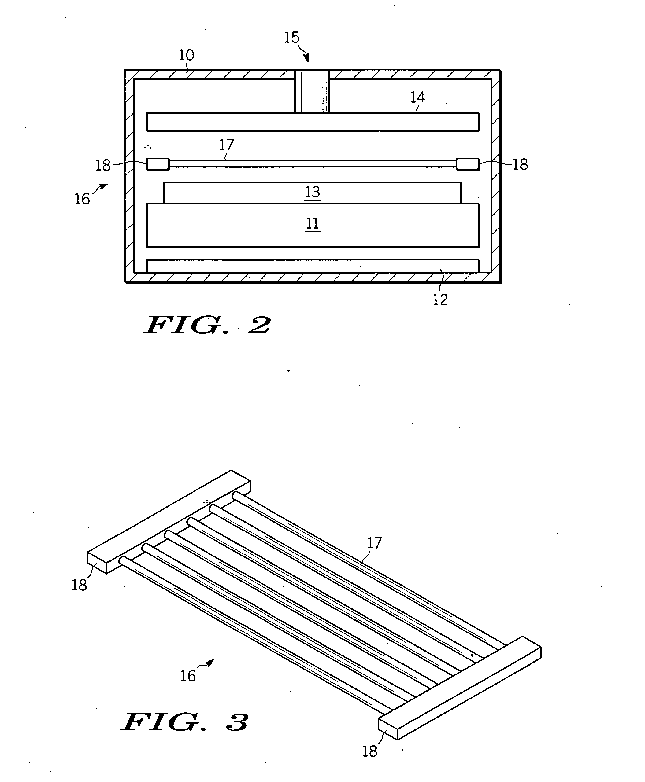
[0044] During a batch HF-CVD process, the HF-CVD reactor is evacuated at a base vacuum pressure in the low 10E-6 Torr by using primary and a turbo-molecular pump package. Once the base pressure in the reactor is reached, the heating element 16, comprising filaments 17 for example, is heated at a temperature preferrably greater than 1500 degree C. The substrate heater 12 is also switched on and allows the substrate 13 temperature to be controlled independently from the filament 17 temperature.

[0045] When the substrate 13 reaches a temperature of 350 degree C., molecular high purity hydrogen gas is flowed through a mass flow controller (MFC—not shown) over the hot filament 17. The pressure in the reactor 10 is controlled by adjusting the throttle valve between the deposition chamber (housing 10) and the vacuum pump (not shown), as well as by the MFC. The MFC provides a way to introduce fixed flow rates of process gases into the HF-CVD reactor. The first step of the carbon nanotube gr...


PUM

PropertyMeasurementUnit
Temperatureaaaaaaaaaa
Chemical propertiesaaaaaaaaaa
Currentaaaaaaaaaa

Abstract

An apparatus is provided for growing high aspect ratio emitters (26) on a substrate (13). The apparatus comprises a housing (10) defining a chamber and includes a substrate holder (12) attached to the housing and positioned within the chamber for holding a substrate having a surface for growing the high aspect ratio emitters (26) thereon. A heating element (17) is positioned near the substrate and being at least one material selected from the group consisting of carbon, conductive cermets, and conductive ceramics. The housing defines an opening (15) into the chamber for receiving a gas into the chamber for forming the high aspect ratio emitters (26).

Description

FIELD OF THE INVENTION [0001] The present invention generally relates to an apparatus and process for selective manufacturing of high aspect emitters and more particularly to an apparatus and process for manufacturing carbon nanotubes over a large surface area. BACKGROUND OF THE INVENTION [0002] Carbon is one of the most important known elements and can be combined with oxygen, hydrogen, nitrogen and the like. Carbon has four known unique crystalline structures including diamond, graphite, fullerene and carbon nanotubes. In particular, carbon nanotubes refer to a helical tubular structure grown with a single wall or multi-wall, and commonly referred to as single-walled nanotubes (SWNTs), or multi-walled nanotubes (MWNTs), respectively. These types of structures are obtained by rolling a sheet formed of a plurality of hexagons. The sheet is formed by combining each carbon atom thereof with three neighboring carbon atoms to form a helical tube. Carbon nanotubes typically have a diamet...

Claims


Application Information

Patent Timeline
IPC IPC(8): C23C16/00
CPCB82Y30/00B82Y40/00C01B31/0233C23C16/44C23C16/50D01F9/127D01F9/133H01J9/025H01J2329/00C01B32/162C01B32/16B82B3/0004B82B3/0009
Inventor COLL, BERNARD F.JOHNSON, SCOTT V.
Owner MOTOROLA INC
Why Eureka
Try Eureka