Welding process for stainless steel piping

a technology of stainless steel piping and welding process, which is applied in the direction of welding/soldering/cutting articles, other domestic articles, manufacturing tools, etc., can solve the problems of stress corrosion cracking in the weld, high cost of heating, and high work and cost. , to achieve the effect of reducing residual stress and suppressing stress corrosion cracking

Inactive Publication Date: 2006-09-14
HITACHI LTD
View PDF8 Cites 48 Cited by
  • Summary
  • Abstract
  • Description
  • Claims
  • Application Information

AI Technical Summary

Benefits of technology

[0018] The present invention has been made in view of the foregoing and it is an object thereof to provide a welding process for stainless steel piping which suppresses stress corrosion cracking by reducing resid

Problems solved by technology

Austenitic stainless steel for use in a welded structure such as a structure, piping, and a component of a nuclear reactor in a boiling water nuclear power plant is known to produce stress corrosion cracking in a weld thereof (such as a weld metal portion and an adjacent portion affected by heat) when it is in contact with high temperature water in the nuclear reactor.
The corrosion environment occurs due to the high temperature water containing dissolved oxygen.
It also requires the work and cost for performing the heating to high temperature and quick cooling.
Patent Document 3 described above is designed to reduce tensile residual stress and welding distortion by the welding procedure with high thermal efficiency and the conductive self-cooling effect of a thin welded joint, but there is a strong possibility that the tensile residual stress does not reach the point where it can be changed into compressive residual stress.
It uses the thin electrode formed in the non-circular shape (the non-circ

Method used


Image

  • Welding process for stainless steel piping
  • Welding process for stainless steel piping
  • Welding process for stainless steel piping

Examples


embodiment 1

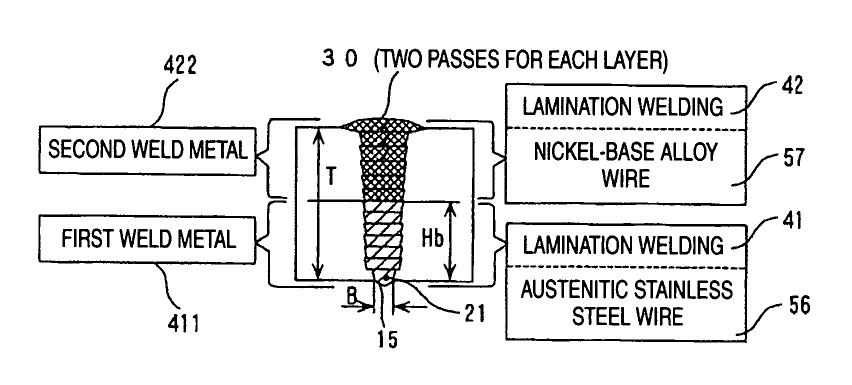
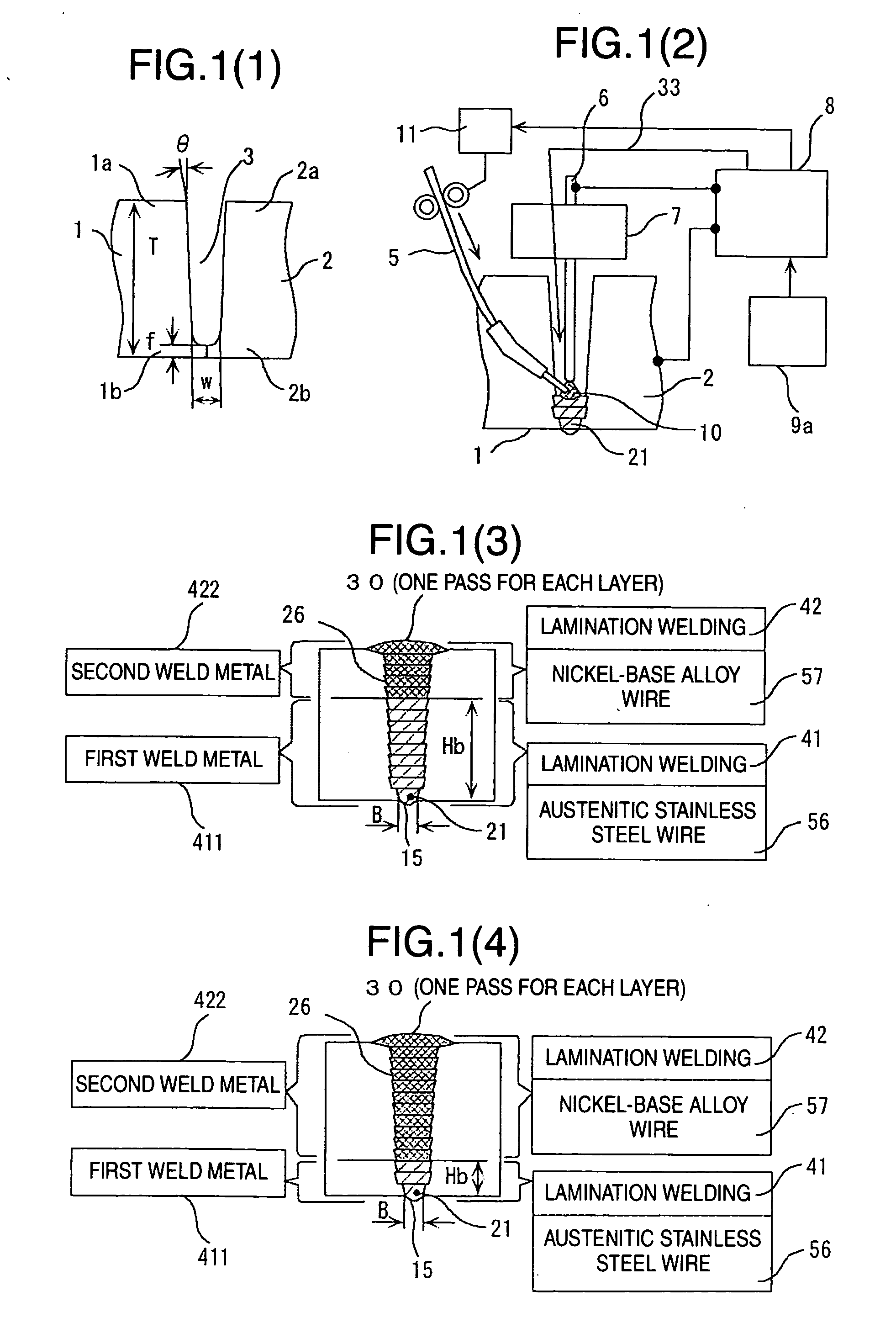
[0084] FIGS. 1(1) to (4) show Embodiment 1 and illustrate the outline of a welding process for austenitic stainless steel piping according to the present invention. FIG. 1(1) shows a cross section of a groove joint member of the piping before welding, FIG. 1(2) is a cross section of the general structure of a welding apparatus during welding, FIG. 1(3) is a cross section in which austenitic stainless steel wire is melted in a groove for lamination welding to a height Hb corresponding to approximately ⅗ of a thickness T from the bottom of the groove, and then the wire is replaced with nickel-base alloy wire for lamination welding to the final layer at the top of the groove from a remaining weld 26, and FIG. 1(4) is a cross section as in FIG. 1(3) in which austenitic stainless steel wire is melted in the groove for lamination welding to a smaller height Hb corresponding to approximately ¼ of the thickness T, and then the wire is replaced with nickel-base alloy wire for lamination weld...

embodiment 2

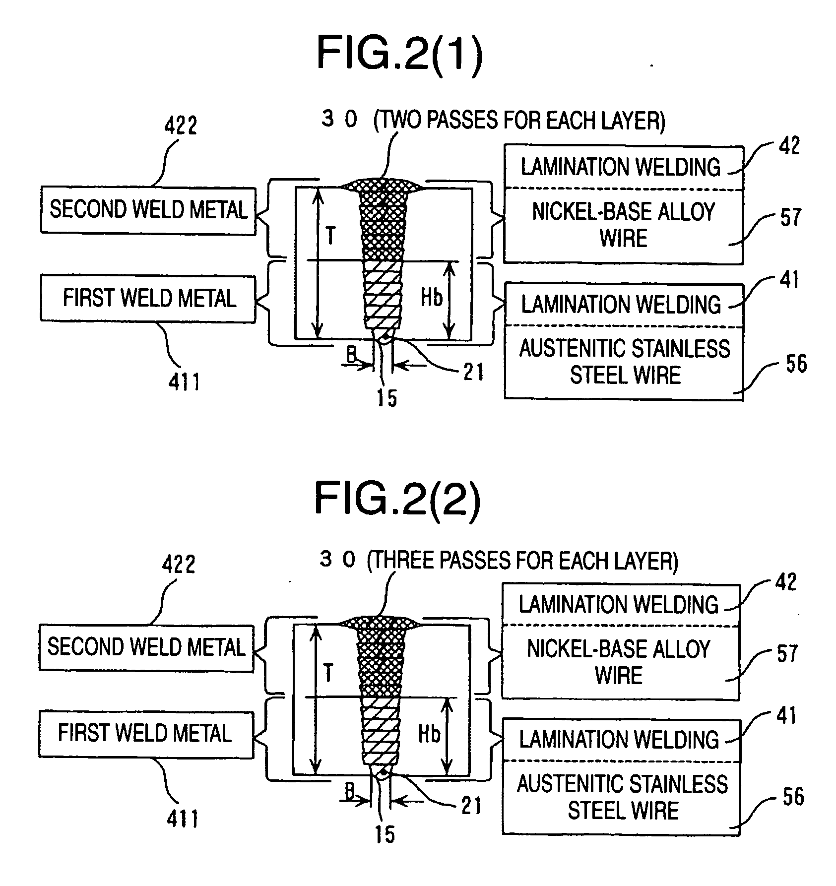
[0097] FIGS. 2(1) and (2) are cross sections in which lamination welding is performed with an increased number of welding passes in Embodiment 2 illustrating a welding process for austenitic stainless steel piping according to the present invention.

[0098] Even when a groove width is so large that welding is not easily achieved by the one layer-one pass welding, or under the same or slightly lower heat input for arc, the one layer-two pass welding can melt both walls having that groove width to provide favorable welding results to the final layer at the top of the groove.

[0099] In addition, the welding passes of the final layer can be increased to three or more to further increase the cumulative bead width of the final layer.

[0100] A second welding metal 422 has a linear expansion coefficient smaller than that of a first welding metal 411 and involves less contraction in the process of solidification after the melting, so that the contraction in the circumferential direction (the ...

embodiment 3

[0101]FIG. 3 is a flow chart for explaining an embodiment of the welding process for austenitic stainless steel piping.

[0102] At first step 51 of manufacturing a groove shape before welding, the joint members to be welded are machined to predetermined dimensions, they are carried to a location for welding, the joint members after processing and parts are assembled, and the like. For example, at the manufacturing step 51, the groove width, the groove wall angle and the like are adjusted.

[0103] Next, at a welding preparatory step 52, welding vehicle 4, welding torch 7, wire 5 and the like are set up. TIG welding power supply 8 and welding controller 9a are activated. Welding operation is prepared and the welding conditions are set. For wire 5, austenitic stainless steel wire 56 made of the same material as that of the welding joint is preferably prepared.

[0104] Then, at a first lamination welding step 41, which includes first layer penetration welding for forming a predetermined ba...


PUM

PropertyMeasurementUnit
Pressureaaaaaaaaaa
Angleaaaaaaaaaa
Widthaaaaaaaaaa

Abstract

The present invention has an object to reduce residual stress in a tensile direction of a weld on the inner side in contact with reactor water of austenitic stainless steel piping, and to change the residual stress into compressive stress, to reduce stress corrosive cracking. The present invention provides a welding process for stainless steel piping of laminating two types of welding wire made of different materials in a groove of austenitic stainless steel piping, including at least one of a first layer penetration welding step of performing a predetermined back bead width on the back side of the groove bottom and a tack welding step, a first lamination welding step of lamination welding of austenitic stainless steel wire from the bottom to the top of the groove, and a second lamination welding step of lamination welding of nickel-base alloy wire to a final layer at the top of the groove.

Description

FIELD OF THE INVENTION [0001] The present invention relates to a process for reducing residual stress in a weld of piping, and more particularly, to a welding process suitable for reducing tensile residual stress in a weld on the inner side of austenitic stainless steel piping in contact with water to suppress stress corrosion cracking. BACKGROUND OF THE INVENTION [0002] Austenitic stainless steel for use in a welded structure such as a structure, piping, and a component of a nuclear reactor in a boiling water nuclear power plant is known to produce stress corrosion cracking in a weld thereof (such as a weld metal portion and an adjacent portion affected by heat) when it is in contact with high temperature water in the nuclear reactor. The stress corrosion cracking is created under conditions in which three factors, that is, sensitization of materials, tensile residual stress, and a corrosive environment, occur together. The sensitization of materials is caused, when chromium carbid...

Claims


Application Information

Patent Timeline
IPC IPC(8): B23K9/04
CPCB23K9/0213B23K2201/06B23K2203/04B23K2101/06B23K2103/05
Inventor OBANA, TAKESHIIMANAGA, SHOJIASHIDA, EIJILUO, XIANGJUNKOIDE, HIROOHANEDA, MITSUAKI
Owner HITACHI LTD
Why Eureka
Try Eureka