Solid electrolytic capacitor and manufacturing method thereof
a technology of solid electrolytic capacitor and manufacturing method, which is applied in the direction of capacitors, capacitor dielectric layers, electrical equipment, etc., can solve the problem of not getting esr sufficiently low in the aforementioned conventional solid electrolytic capacitor
- Summary
- Abstract
- Description
- Claims
- Application Information
AI Technical Summary
Benefits of technology
Problems solved by technology
Method used
Image

Examples
example 1
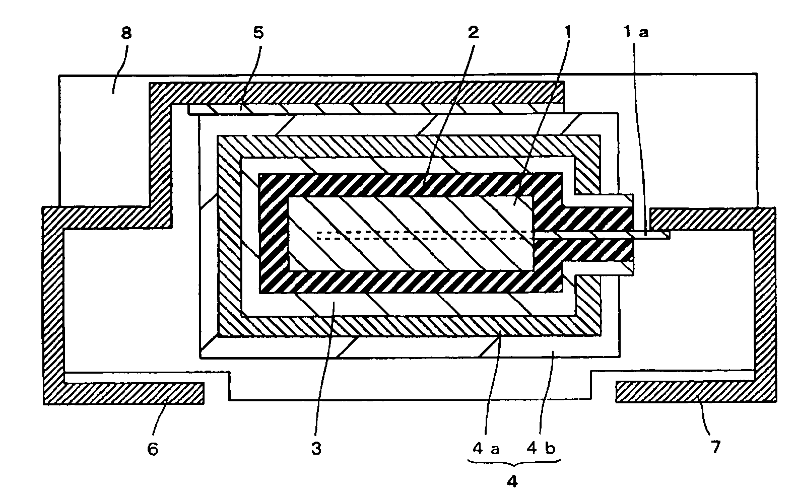
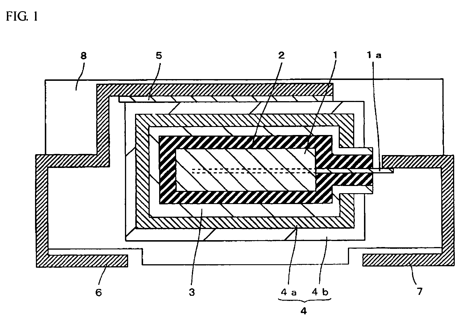
[0021] A structure of a solid electrolytic capacitor according to example 1 of the present invention is now described with reference to FIG. 1.
[0022] First, in the solid electrolytic capacitor according to example 1 of the present invention, a plate-shaped anode 1 is formed covering one part of an anode lead 1a of tantalum, as shown in FIG. 1. Anode 1 has a porous sintered body of tantalum prepared by sintering tantalum particles having an average particle diameter of about 2 μm in a vacuum. Tantalum is an example of the “metal” forming the anode in the present invention.
[0023] A dielectric layer 2 of tantalum oxide is formed covering anode 1. An electrolyte layer 3 of tantalum carbide is formed covering dielectric layer 2. Tantalum carbide is an example of the “metal carbide having the interstitial structure” in the present invention.
[0024] A cathode 4 is formed covering electrolyte layer 3. Cathode 4 is formed by a first conductive layer 4a mainly containing graphite particles ...
example 2
[0035] In this example 2, solid electrolytic capacitors having the same structure as that in example 1 are fabricated except that electrolyte layers 3 are formed of niobium carbide, titanium carbide, zirconium carbide, hafnium carbide, vanadium carbide and tungsten carbide instead of electrolyte layer 3 of tantalum carbide in the aforementioned example 1. Niobium carbide, titanium carbide, zirconium carbide, hafnium carbide, vanadium carbide and tungsten carbide are examples of the “metal carbide having the interstitial structure” in the present invention respectively.
[0036] In this example, electrolyte layers 3 are formed in the same manner as in example 1 except that ethanol of about 1 wt % niobium complex, titanium complex, zirconium complex, hafnium complex, vanadium complex and tungsten complex with porphyrin as ligands are used respectively. Niobium complex, titanium complex, zirconium complex, hafnium complex, vanadium complex and tungsten complex are examples of the “organo...
example 3
[0040] Solid electrolytic capacitors are fabricated in the same manner as in example 1 except that ethanol containing tantalum complexes with phthalocyanine (C32H16N8), ethylenediaminetetraacetic (C10H16N2O8, EDTA) and citric acid (C6H10O8) as ligands are used instead of ethanol containing tantalum complex with porphyrin as a ligand in example 1 respectively.
[0041] The solid electrolytic capacitors formed in this example are measured for ESR at a frequency of about 100 kHz using an LCR meter by means of applying voltage between cathode terminal 6 and anode terminal 7. The results are shown in Table 2.
TABLE 2LigandESRExample 1Porphyrin15.1 mΩExample 3Phthalocyanine15.2 mΩEDTA15.5 mΩCitric acid18.0 mΩComparative example 1—21.0 mΩ
[0042] ESR in the solid electrolytic capacitors of example 3 is less than ESR in the solid electrolytic capacitor of the comparative example 1, as shown in Table 2. Especially, ESR become less in the case of ligands of organometallic complexes are made up o...
PUM
| Property | Measurement | Unit |
|---|---|---|
| conductivity | aaaaa | aaaaa |
| conductivity | aaaaa | aaaaa |
| conductivity | aaaaa | aaaaa |
Abstract
Description
Claims
Application Information
PatSnap Eureka turns technology decisions into work you can execute. Powered by our Innovation Knowledge Graph, it runs expert workflows across engineering, life sciences, materials and intellectual property. Get your review-ready output in minutes.


