Method for obtaining nanoparticles

a nanoparticle and nanoparticle technology, applied in the direction of solid-state diffusion coating, plasma technique, transportation and packaging, etc., can solve the problems of inability to design efficient nanoelectronics, inability to use structures of this kind inability to use structures such as structures to create catalysts operating in the maximum efficiency mode, etc., to achieve the effect of high density of nanoparticle packing and increasing the efficiency of conversion of starting materials

Active Publication Date: 2006-10-05
GUREVICH +2
View PDF0 Cites 69 Cited by
  • Summary
  • Abstract
  • Description
  • Claims
  • Application Information

AI Technical Summary

Benefits of technology

[0020] The aim of the claimed invention is to modify the known prototype method by developing such a procedure for obtaining nanoparticles that could be used to deposit onto the surface of a support nanoparticles with a narrow size dispersion and amorphous structure, which makes it possible to achieve an exceedingly high density of nanoparticle packing. The improvement of the known prototype method also includes raising the efficiency of conversion of the starting material into nanoparticles.
[0032] The essence of the invention consists in that, in contrast to the known prototype method, the parameters of the plasma used are chosen to meet the requirement that conditions (1)-(3) should be satisfied simultaneously. These conditions ensure a cascade fission of all the initial liquid drops of the material, injected into the plasma, and a fast cooling of the forming liquid nanometer-size drops (final products of drop fission), such that the solid nanoparticles deposited onto the substrate have an amorphous structure. If these conditions are satisfied, monodispersive structures composed of amorphous nanoparticles with variable (including an exceedingly high) packing density can be reproducibly formed, with an efficient conversion of the starting material into nanoparticles.

Problems solved by technology

Accordingly, exchange of electrons between neighboring particles is hardly probable and it is impossible to use structures of this kind to create catalysts operating in the maximum efficiency mode and to design efficient nanoelectronic devices in which the effects of interaction and charging of densely packed particles are important.
The method cannot be used to form silicon nanostructures in local regions because it transforms the zeolite substrate across virtually its whole thickness.
However, as the content of metal increases, the catalytic activity of catalysts of this kind decreases because crystalline nanoparticles formed by this technique coagulate when coming in contact with one another.
Among disadvantages of the method are its low output capacity and relatively wide particle size dispersion.
Moreover, the method gives no way of forming metallic particles with high density of particle packing, because, as the density increases, crystalline nanoparticles coagulate into more bulky formations.
However, the conditions that could ensure stable formation of nanoparticles with amorphous structure have not been determined for the prototype method.
This also hinders the industrial application of the prototype method.
The coalescence of crystalline nanoparticles gives rise to severe difficulties in formation of structures with a high density of particle packing.

Method used


Image

  • Method for obtaining nanoparticles
  • Method for obtaining nanoparticles
  • Method for obtaining nanoparticles

Examples


example 1

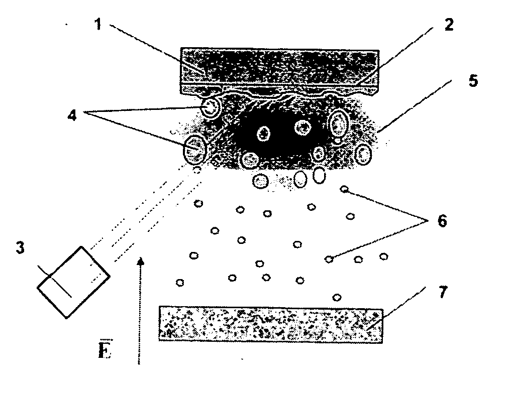
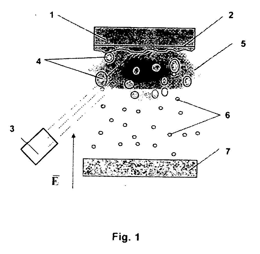
[0054] The claimed method for obtaining nanoparticles was practiced on the basis of laser dispersion of such metals as copper and nickel (see FIG. 1). In this case, irradiation of the surface of the metallic target 1 with a pulsed-periodic laser 3 leads to melting of the surface layer 2 of the target 1 and the material of the target 1 evaporates. As a result of an optical breakdown of the vapor formed, a plasma zone 5 with a thickness L≧100 μm is formed near the surface of the molten layer 2 of the target 1. Under the action of plasma 5, the molten surface layer 2 becomes unstable, which leads to dispersion of the metal to give liquid particles 4 from the metal of the target 1, with the maximum and minimum radii of these particles being R=1 μm and r=100 nm, respectively. Liquid drops 4 formed as a result of dispersion are fed into the plasma zone 5, which is heated by absorbed laser light. In the plasma zone 5, drops 4 are charged to the floating potential, so that their charge is m...

example 2

[0059] The claimed method was practiced on the basis of an installation for plasma-assisted electrodispersion, which is shown schematically in FIG. 4. Molten metal was dispersed by applying to a metallic pointed cathode 9 with a radius of tip curvature not exceeding 10 μm an electric field with a strength at the tip apex of no less than 107 V / s.

[0060] Molten drops 4 obtained at the tip 8 are delivered to the plasma zone 5 created by a stationary or quasi-stationary discharge in an inert gas at a pressure of 10−3-10−1 Pa, to be charged there. The electron density in stationary discharges at these pressures is on the order of ne=1010-1011 cm−3, and, in accordance with condition (1), the required temperature of electrons should exceed 500 eV. To create such a temperature, the potential difference between anode 9 and cathode 10 was set to be no less than 2 kV.

[0061] For drops 4 not to have enough time to be charged to the floating potential, i.e., for condition (2) to be satisfied at ...


PUM

PropertyMeasurementUnit
grain sizeaaaaaaaaaa
sizeaaaaaaaaaa
power densityaaaaaaaaaa

Abstract

The method is intended for obtaining nanosize amorphous particles, which find use in various fields of science and technology; in particular, metallic nanostructures can be regarded as a promising material for creating new sensors and electronic and optoelectronic devices and for developing new types of highly selective solid catalysts. The method for obtaining nanoparticles includes the following stages: dispersion of a molten material; supply of the resulting liquid drops of this material into a plasma with parameters satisfying the aforementioned relationships, which is formed in an inert gas at a pressure of 10−4-10−1 Pa; cooling of liquid nanoparticles formed in the said plasma to their hardening; and deposition of the resulting solid nanoparticles onto a support.

Description

RELATED APPLICATIONS [0001] This application is a Continuation of PCT application serial number PCT / IB2004 / 051445 filed on Aug. 10, 2004 which in turn claims priority to Russian application serial number RU2003127822 filed on Sep. 9, 2003, both of which are incorporated by reference herein in their entirety.FIELD OF THE INVENTION [0002] The invention is intended for obtaining nanosize particles that find application in various fields of science and technology; in particular, metallic nanostructures are regarded as a promising material for development of new sensors and electronic and optoelectronic devices and for design of new types of highly selective solid-state catalysts. BACKGROUND OF THE INVENTION [0003] As shown in a number of recent publications, nanostructures with a surface particle density on the order of 1012 cm−2 are promising for development of efficient nanoelectronic devices, such as ultrafast switches or subminiature memory cells (K.-H. Yoo, J. W. Park, J. Kim, K. S...

Claims


Application Information

Patent Timeline
Patent Type & Authority Applications(United States)
IPC IPC(8): H05H1/24C23C8/00C23C4/00B01J2/02B22F1/054B22F1/08B22F9/00B22F9/08B22F9/14
CPCB22F1/0018B22F9/008B22F9/082B22F9/14B22F2999/00B82Y30/00B22F2202/13B22F1/054B22F1/08
Inventor GUREVICHKOZHEVIN, VLADIMIR M.YAVSIN, DENIS A.
Owner GUREVICH
Why Eureka
Try Eureka