
Method of forming conductive film and method of manufacturing electronic apparatus

Inactive Publication Date: 2006-10-26
SEIKO EPSON CORP
View PDF6 Cites 15 Cited by
  • Summary
  • Abstract
  • Description
  • Claims
  • Application Information

AI Technical Summary

Benefits of technology

[0007] An advantage of some aspects of the invention is that it provides a method of forming a conductive film having low resistance and stable electric characteristics by using a liquid phase method.
[0009] In the conductive film forming method, the light-irradiation treatment using a flash lamp is carried out when the liquid material is baked to obtain a conductive film composed of a particle sintered film. Accordingly, the liquid material is instantly heated to rapidly remove the dispersion medium in which the particulate materials are dispersed. Further, since the sintering of the particulate materials is performed by heat energy and light energy, it is possible to form a conductive film having a more stable conduction state, compared with a method according to the related art in which sintering is performed only by heat energy. This is because the crystallinity of the particle surface can be recovered by the assistance of light energy, and the necking or adhesion between the particles is stimulated by the light energy.
[0010] In the conductive film forming method, the particulate materials may be particles of a conductive material of which the bulk melting point is higher than 900° C., and of which the melting point in a particle diameter of 10 to 150 nm is higher than 255° C. In such a material which has a high melting point and in which the depression of melting point is small when it is microparticulated, when a conductive film is formed by using a liquid phase method in order to limit the heating temperature, the adhesion or sintering between particles is not sufficiently performed, and it is difficult to obtain a conductive film having an excellent electric characteristic. Therefore, the application of the forming method according to the invention stimulates the fusion bond between particles to obtain stable conduction, and is extremely effective even when a conductive film is formed by using the particulate materials having a high melting point.
[0012] Furthermore, in the conductive film forming method, the transparent conductive material may be at least one metal oxide which is selected from indium tin oxide, tin oxide, oxidized indium, indium zinc oxide, and halogen-containing tin oxide. The invention is particularly effective when a conductive film using the particles of those transparent conductive materials is formed.
[0015] According to another aspect of the invention, a method of manufacturing an electronic apparatus is provided which includes a conductive film forming process using the forming method according to the above aspects. In accordance with the manufacturing method, an electronic apparatus which is provided with a stable conductive film and is excellent in electrical reliability can be manufactured at low cost.

Problems solved by technology

However, the ITO film obtained by the forming method has large sheet resistance and is not suitable for electrode application.
In the conductive film forming method, the particulate materials may be particles of a conductive material of which the bulk melting point is higher than 900° C., and of which the melting point in a particle diameter of 10 to 150 nm is higher than 255° C. In such a material which has a high melting point and in which the depression of melting point is small when it is microparticulated, when a conductive film is formed by using a liquid phase method in order to limit the heating temperature, the adhesion or sintering between particles is not sufficiently performed, and it is difficult to obtain a conductive film having an excellent electric characteristic.
Therefore, it is difficult to perform the fusion bond or sintering through heating and to obtain a stable electric characteristic.
In the metallic materials, the surface oxidation easily occurs in the air, and it is difficult to perform the fusion bond between the particles by heating and to obtain a stable electric characteristic.

Method used


Image

  • Method of forming conductive film and method of manufacturing electronic apparatus
  • Method of forming conductive film and method of manufacturing electronic apparatus
  • Method of forming conductive film and method of manufacturing electronic apparatus

Examples


Embodiment Construction

Method of Forming Conductive Film

[0038] Hereinafter, preferred embodiments of the invention will be described with reference to the drawings.

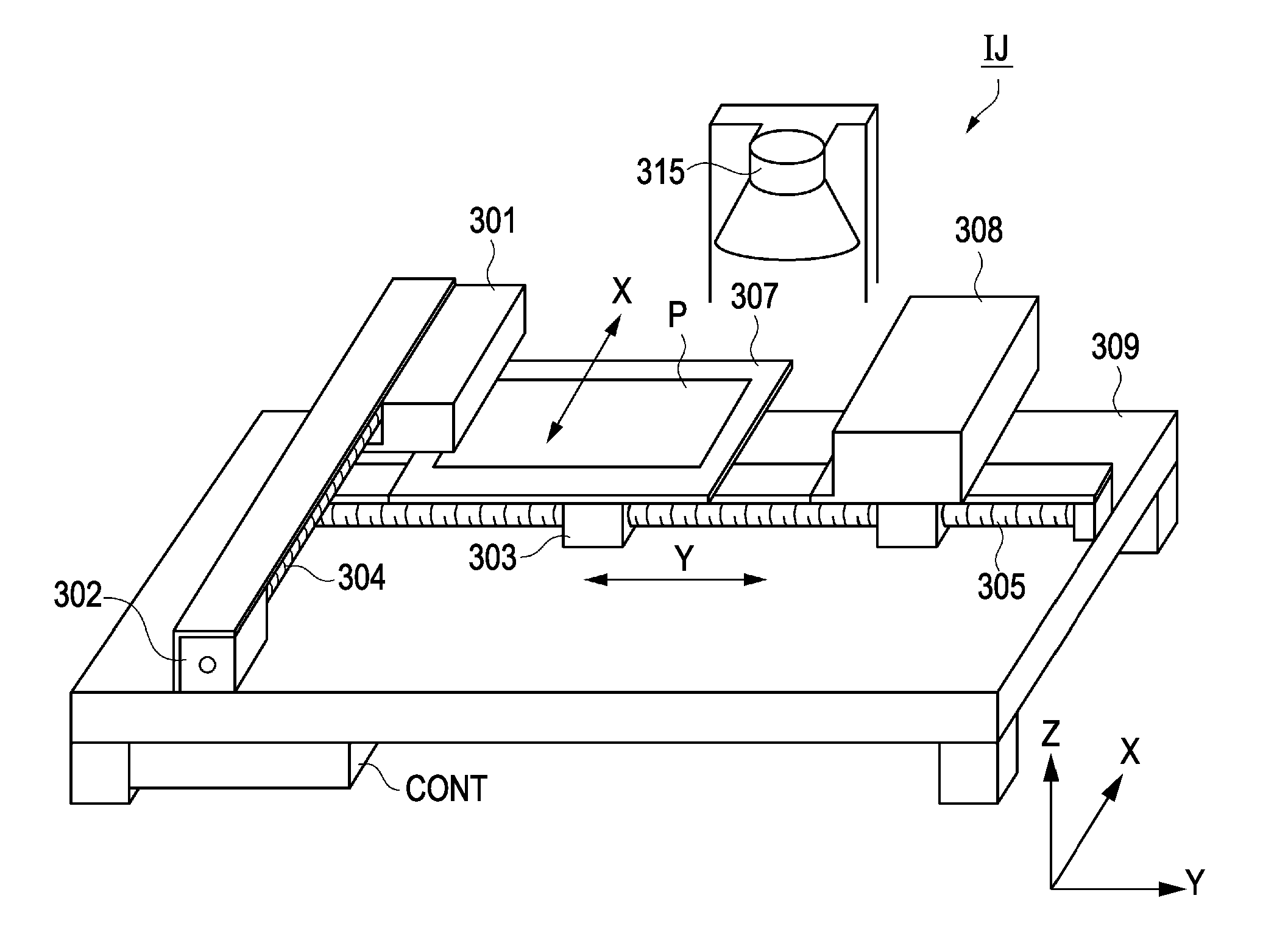
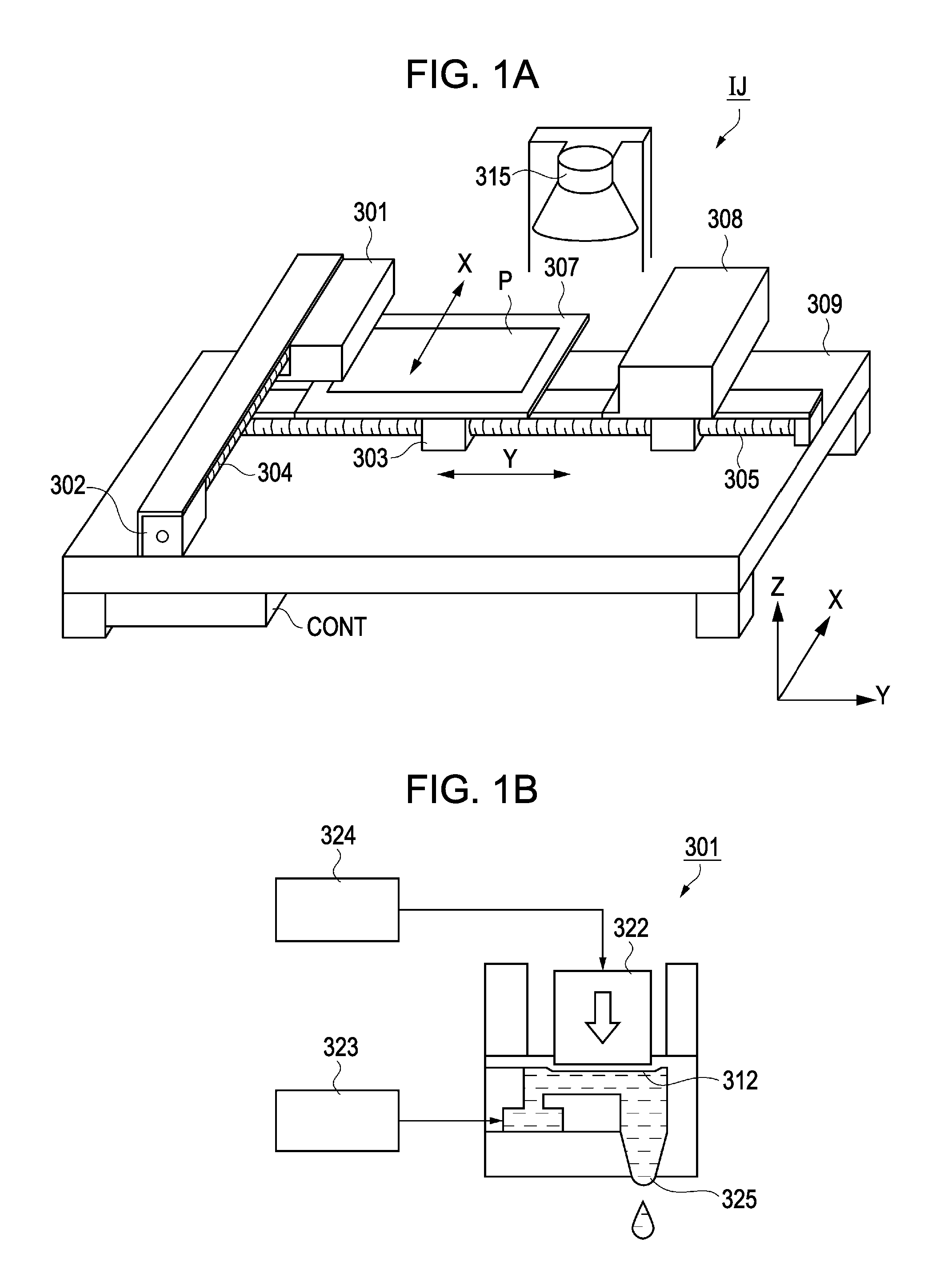
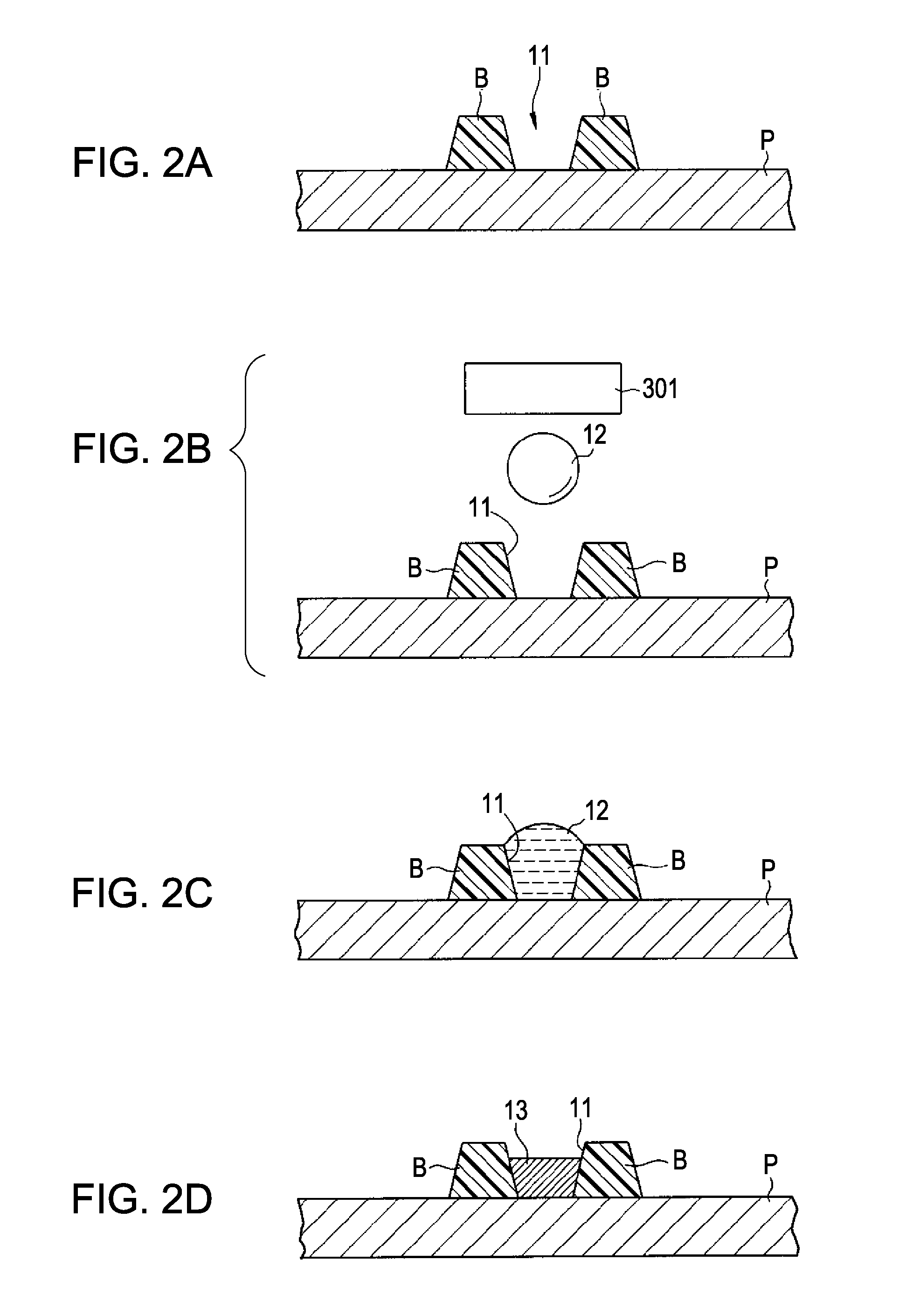
[0039]FIG. 1A is a schematic view illustrating a droplet discharge device which is used in a forming method according to the present embodiment, and FIG. 1B is a cross-sectional view for explaining the method of forming a conductive film. FIGS. 2A to 2D are cross-sectional views for explaining a conductive film forming method according to an embodiment.

Liquid Material

[0040] In the present embodiment, a case will be described, in which liquid material including particulate material is disposed on a substrate by using a droplet discharge method, and after, a conductive film pattern is formed. As the liquid material which is used in the forming method according to the present embodiment, material obtained by dispersing particulate material into a dispersion medium is used. A conductive film forming material which is suitable for forming a co...


PUM


Abstract

A method of forming a conductive film includes disposing liquid material containing particulate materials on a substrate, and baking the liquid material on the substrate through light-irradiation using a flash lamp so as to form a conductive film.

Description

BACKGROUND [0001] 1. Technical Field [0002] The present invention relates to a method of forming a conductive film and to a method of manufacturing an electronic apparatus. [0003] 2. Related Art [0004] A conductive film (optically-transparent conductive film) is used in an electrode of an electro-optical device, an electrode of a touch panel, an electromagnetic wave shielding material, or the like. As a representative example, an indium tin oxide (ITO) doped with tin is known. In general, an ITO film is generally formed by using an evaporation method or sputtering method. However, in order to remarkably reduce manufacturing cost and to collectively form a film on a large area, a method of forming an ITO film using a liquid phase method has been examined. [0005] For example, JP-A-2001-2954 discloses a method of forming an ITO film through a liquid phase method using liquid material in which an indium organic acid compound and an organic tin compound are melted in an organic solvent. ...

Claims


Application Information

Patent Timeline
IPC IPC(8): C30B19/00
CPCG02F2001/136295H05K3/0082H05K3/02H01L2224/742H05K2201/0257H05K2203/0557H01L2224/11334H05K3/12G02F2202/36G02F1/136295H01L2924/12044H01L2924/00H01B13/00
Inventor DENDA, ATSUSHI
Owner SEIKO EPSON CORP
Learn More