[0010] The present invention is a hermetic cavity in which information and / or energy can be transmitted through the walls of the cavity without the need to form a physical breach of the wall of the cavity. A particularly useful embodiment of the invention is a sensor that is comprised of a sensor body which defines a hermetic cavity. All sensing elements associated with the sensor are located within the hermetic cavity and therefore are hermetically sealed from the surrounding environment, thereby reducing drift and
instability of the sensor. Electrical communication between the sensing elements and
electronics external to the hermetic chamber is accomplished by means of
electromagnetic coupling between two complementary conductors located on opposite sides of at least one wall defining the hermetic cavity.
[0012] Sensors of the present invention are entirely self-packaged and maintain electrical communication with the surrounding environment without the need for electrical feedthroughs breaching the hermetic cavity.
Elimination of feedthroughs into the hermetic cavity increases reliability and durability of the sensor by eliminating a feature that is frequently cited as a point of failure of hermeticity in such devices. The sensor can be fabricated using high-purity, hermetic and biocompatible materials, e.g., ceramics, metals and polymers. If ceramics are used to construct the sensor body defining the hermetic cavity, the
ceramic substrates can be fused together so that there is no interface of material remaining where the substrates have been joined to create a cavity. This eliminates any material interface in the sensor body that could become the site of a potential leak path into the hermetic cavity and, consequently, increases the reliability and durability of the sensor. Alternatively, anodic or
eutectic bonding techniques can be utilized to create the hermetic cavity. Furthermore, sensors of the present invention can be manufactured using
microelectromechanical systems (MEMS) fabrication techniques, which allow creation of a device that is small, accurate, precise, durable, robust, biocompatible, and insensitive to changes in body
chemistry or
biology.
[0015] In another embodiment of the invention, the hermetic cavity is further configured to be sensitive to a selected range of pressure. The pressure cavity (i.e., this pressure-sensitive hermetic cavity) further comprises a
capacitor configured so that the characteristic
capacitance value of the
capacitor indicates a physical state, or changes in a physical state, within a patient. The electrodes of the
capacitor are substantially planar and are arranged substantially parallel to and spaced apart from one another. The pressure cavity has at least one deflectable region in mechanical communication with at least one of the capacitor electrodes. In this embodiment, the capacitor and
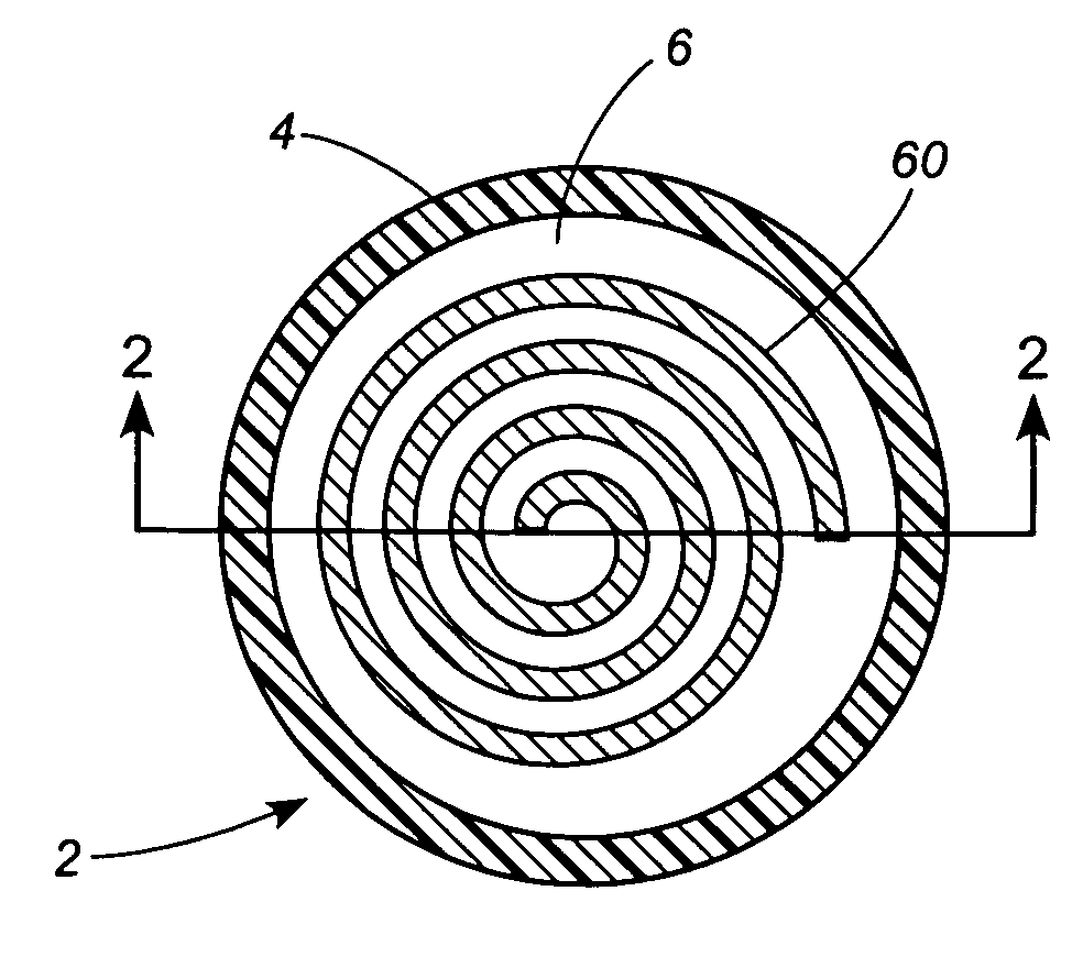
inductor are realized through mutually-imposed, planar
spiral inductor coils located on opposite sides of the pressure cavity with at least a portion of one of the planar spiral coils fixed to the deflective region. The
inductance and
capacitance of the circuit are distributed across the area of the mutually-imposed coils. The spiral coils can, optionally, terminate in electrodes. This feature increases the
capacitance of the circuit and allows the resonant frequency of the circuit to be tuned by varying the size of the electrodes. Another mutually-imposed, planar
spiral inductor coil is located external to the pressure cavity in magnetic proximity to the internal
spiral inductor coils. This external
inductor coil is isolated from the surrounding environment by
coating it with a suitable
polymer or encasing it in a
ceramic material. In either case, wires or electrical feedthroughs terminating in bond pads are provided so that connection of the sensor to other
electronics can be established.
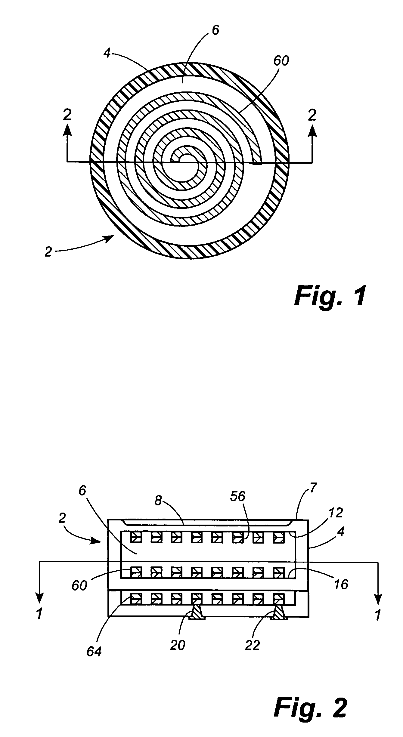
[0017] In yet another embodiment, a wired sensor further comprises on-board (i.e., within the sensor
package) electronics, e.g., a
silicon chip bearing electronics. This embodiment has the
advantage of reduced sensitivity to external electromagnetic effects introducing spurious signals on the leads of the previous embodiments, especially if such leads are long. The variable capacitive element and the on-board electronics can be maintained in separate cavities in electrical communication with one another by opposed
inductor coils located on either side of a middle substrate. Feedthroughs establishing electrical communication between the interior of the second chamber and the ambient are provided in this case. Such feedthroughs are configured so that
moisture does not affect the electronics over the life of the sensor and, optionally, are hermetic.

