[0016] The heat treatment method of the present invention is able to perform heating in a short time to a prescribed temperature in a range from approximately 800° C. to 2600° C., preferably from approximately 1200° C. to 2300° C., thereby making it possible to create a new material which has not been provided by conventional heat treatment equipment.
[0019] Then, the heat treatment method used in the liquid phase epitaxial method for growing
single crystal silicon carbide of the present invention is a method, wherein the closed container is in advance heated to a temperature exceeding approximately 800° C. in a preheating chamber kept in a high vacuum at a pressure of approximately 10−5 Pa or lower, and the closed container is reduced in pressure to approximately 10−5 Pa or lower, the container is transported and placed in the heat chamber, which is in advance heated to a prescribed temperature in a range from approximately 1400° C. to 2300° C., in a vacuum at a pressure of approximately 10−2 Pa or lower, preferably at a pressure of 10−5 Pa or lower or in a rarefied gas
atmosphere to which some
inert gas is introduced after a prior arrival at a high vacuum at a pressure of 10−5 Pa or lower, by which the monocrystal silicon carbide substrate and the polycrystal silicon carbide substrate are heated in a short time to a prescribed temperature in a range from approximately 1400° C. to 2300° C. to produce
single crystal silicon carbide which is free of
fine grain boundaries and approximately 1 / cm2 or lower in density of
micropipe defects on the surface.
[0020] As explained so far, the above method is able to perform heating in a short time to a prescribed temperature in a range from approximately 1400° C. to 2300° C., thereby making it possible to produce single crystal SiC effectively. In addition, since the thus produced single crystal SiC is free of
fine grain boundaries inside crystals grown and approximately 1 / cm2 or lower in density of micropipe defects on the surface, it can be used in various types of
semiconductor devices. In this instance, micropipe defects are also called pin holes, referring to a tubular cavity in a
diameter of several μms or lower present along the direction of
crystal growth. Any
crystal plane of 4H—SiC and 6H—SiC may be used as a monocrystal
SiC substrate which is a
seed crystal to be used in the invention, but it is preferable to use (0001) Si plane. As a polycrystal
SiC substrate, it is preferable to use a plane which is from approximately 5 μm to 10 μm in mean grain size and uniform in grain size. Therefore, there is no particular limit to the
crystal structure of polycrystal SiC, and any of 3C—SiC, 4H—SiC and 6H—SiC may be used. However, preferable is 3C—SiC.
[0021] Further, according to the present invention, during heat treatment, Si is permeated as
wetting into every part of the interface between A monocrystal
SiC substrate and a polycrystal SiC substrate by capillarity, thereby forming a very thin metallic Si melt layer. C atoms which flow from the polycrystal SiC substrate are supplied through the Si melt layer to the monocrystal SiC substrate to provide liquid phase epitaxial growth as single crystal SiC on the monocrystal SiC substrate. Therefore, defects which may take place from an initial stage of growth to a completion stage can be prevented. In addition, the present invention makes it possible to greatly reduce a quantity of Si adhered on the monocrystal SiC substrate as a seed crystal after heat treatment and on the polycrystal SiC substrate, which is removed after heat treatment, without the necessity for immersion treatment of the substrates into Si melt, which is required by a conventional method. Further, a very thin metallic Si melt layer is interposed between the monocrystal SiC substrate and the polycrystal SiC substrate during heat treatment, thus making it possible to use only metallic Si necessary for epitaxial growth of single crystal SiC in performing liquid phase epitaxial growth of single crystal SiC. Therefore, the thin Si layer can provide a minimum contacting area with the outside during heat treatment, thereby reducing a possible inclusion of impurities to produce high-purity single crystal SiC.
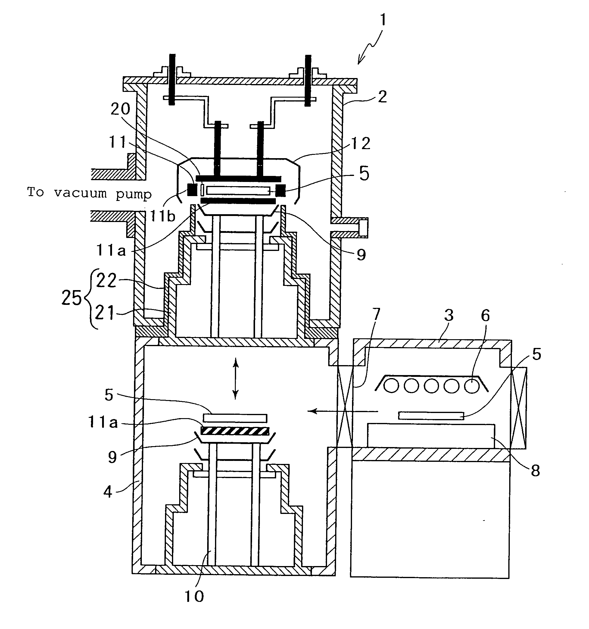
[0022] The heat treatment equipment of the present invention comprises a heat chamber wherein a substance to be treated is heated in a short time to a prescribed temperature in a range from approximately 1200° C. to 2300° C. in a vacuum at a pressure of approximately 10−2 Pa or lower, preferably approximately 105 Pa or lower, or in a rarefied gas
atmosphere to which an
inert gas is introduced after a prior arrival at a vacuum at a pressure of approximately 10−2 Pa or lower, or preferably approximately 10−5 Pa or lower, an anterior chamber connected to the heat chamber and equipped with a transportation means for transporting the substance to be treated to the heat chamber, and a preheating chamber connected to the anterior chamber for heating in advance the substance to be treated to a temperature exceeding approximately 800° C. in a vacuum at a pressure of approximately 10−2 Pa or lower, preferably at a pressure of approximately 10−5 Pa or lower.
[0023] The heat treatment equipment of the present invention comprises a high-temperature
heating furnace wherein the inside of a vacuum high-temperature furnace is composed of two or more divided tanks, the inside of each of these plurality of tanks is constituted with a main heating tank and a preheating tank, the preheating tank is heated from a
room temperature to approximately 800° C. for degassing the gas mainly adsorbed to a sample and the gas contained inside the sample, after completion of the degassing, the sample is smoothly transported to the main heating tank which is in advance discharged of air by heating and vacuum treatment and kept clean and at high temperatures, the main heating tank is constantly heated to a prescribed high temperature in a range from approximately 800° C. to 2600° C. constantly at a pressure of approximately 10−3 Pa or lower or in a rarefied gas atmosphere at any given pressure from
ambient pressure to approximately 10−3 Pa by introduction of some
inert gas after a prior arrival at approximately 10−3 Pa or lower pressure, the preheating tank has the function of discharging air from
ambient pressure for supplying and removing a sample to a
pressure level which is the same as that attained by the main heating tank necessary for transporting the sample to or from the main heating tank, and after a preheating of the sample from
room temperature to approximately 800° C., a quick transportation to the main heating tank enables to attain a high-temperature and high-purity atmosphere at a prescribed temperature in a range from approximately 800° C. to 2600° C. which is an optimal temperature for treating the sample.

