

Method and apparatus for fine particle liquid suspension feed for thermal spray system and coatings formed therefrom
a technology of liquid suspension feed and thermal spray system, which is applied in the direction of cell components, sustainable manufacturing/processing, and final product manufacturing, etc., can solve the problems of limited feed rate of suspension feed, limited use of large feedstock powder, and conventional plasma spraying techniques, so as to improve the protection against obstruction and easy application
- Summary
- Abstract
- Description
- Claims
- Application Information
AI Technical Summary
Benefits of technology
Problems solved by technology
Method used
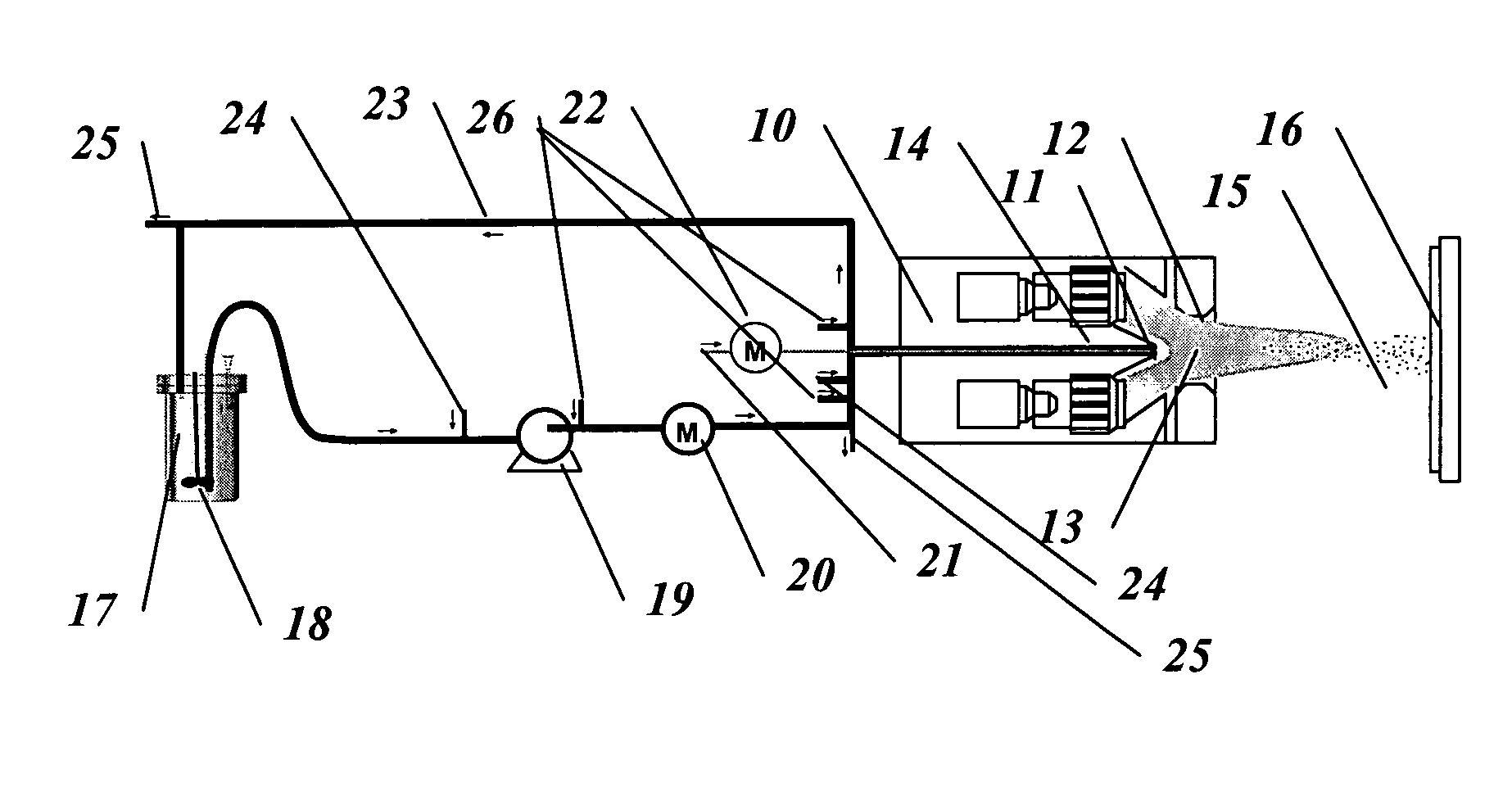
Image

Examples
example 1
[0042] In this example Y2O3—ZrO2 oxide coatings, which can be applied as thermal barrier coatings (TBC) or solid oxide fuel cell (SOFC) components, were prepared on mild-steel substrates. The suspensions of 10 wt % solids in ethanol was prepared from 1.5 wt % yttria doped ZrO2 powder (29-80 nm particle size), and dispersed in a two-frequency ultrasonic bath at 16 and 80 kHz, without addition of a dispersant. The suspension was injected into the spray torch a flow rate 34.7 ml / min and propelled through the injection orifice of this invention with a diameter of 0.5 mm with nitrogen gas propellant at a flowrate of 5.0 slpm. FIG. 3 shows a photograph of the suspension jet propelled through in injector orifice without the plasma. The converging nozzle was removed for this photograph. During deposition, the substrate temperature was maintained at approximately 200° C. using forced air-cooling. Experimental conditions were as following:
Torch Current (3×)180ATotal primary gas flow rate180...
example 2
[0045] In this example, Al2O3 oxide coatings and composite coatings were prepared on mild-steel substrates. The suspensions of 10 wt % solids in ethanol are prepared from α—Al2O3 powder (29-68 nm particle size), and dispersed in an ultrasonic bath, as elaborated in Example 2. A suspension of 57 wt % Al2O3 and 43% ZrO2 (1.5% Yttria) was also prepared by mixing Al2O3 and ZrO2 feedstocks. At this ratio, a eutectic alloy exists. The Al2O3 and Al2O3—ZrO2 suspensions were injected into the spray torch at flow rates of 35 ml / min and 34.7 ml / min, respectively. The suspensions were propelled through a 0.5 mm diameter injection orifice, using nitrogen gas at a flowrate of 5.0 slpm. For the purpose of illustration, this example uses the same spray conditions as listed in Example 1. However, the substrate temperature for the alumina coating was maintained at 400° C., and for the alumina-zirconia composite coatings at 300° C. Particle velocities around 500 m / sec and particle temperatures of 2700...
example 3
[0049] In this example, samarium doped ceria electrolytes for an intermediate temperature solid-oxide fuel cell (SOFC) were produced. SOFC electrolytes are traditionally made of yttria-stabilized zirconia (YSZ) and operate at high temperatures, typically around 900-1000° C. Reducing the operating temperature can significantly decrease the component cost. This would drastically lower the material costs for components like interconnects and insulation. New materials, such as gadolinium or samarium-doped ceria ceramics (CGO or SDC) have higher conductivity at lower temperatures. Furthermore, a thin and nanostructured electrolyte layer can compensate for the reduction of ionic conductivity at lower temperatures by decreasing the traveling distance for oxygen ions and enhancing the mobility of the ions along the grain boundaries. In contrast to traditional processes, such chemical vapor deposition (CVD), physical vapor deposition (PVD) and casting, plasma spraying is highly cost-effectiv...
PUM
| Property | Measurement | Unit |
|---|---|---|
| flow rates | aaaaa | aaaaa |
| flow rates | aaaaa | aaaaa |
| inner diameter | aaaaa | aaaaa |
Abstract
Description
Claims
Application Information