Insulating ceramic composition, insulating ceramic sintered body, and multilayer ceramic electronic component

a technology of insulating ceramics and electronic components, applied in the direction of fixed capacitors, natural mineral layered products, solid-state devices, etc., can solve the problems of downsized electronic devices, achieve stable temperature coefficient (f), reduce the relative dielectric constant, and reduce the effect of dielectric constan

Inactive Publication Date: 2006-12-28
MURATA MFG CO LTD
View PDF6 Cites 27 Cited by
  • Summary
  • Abstract
  • Description
  • Claims
  • Application Information

AI Technical Summary

Benefits of technology

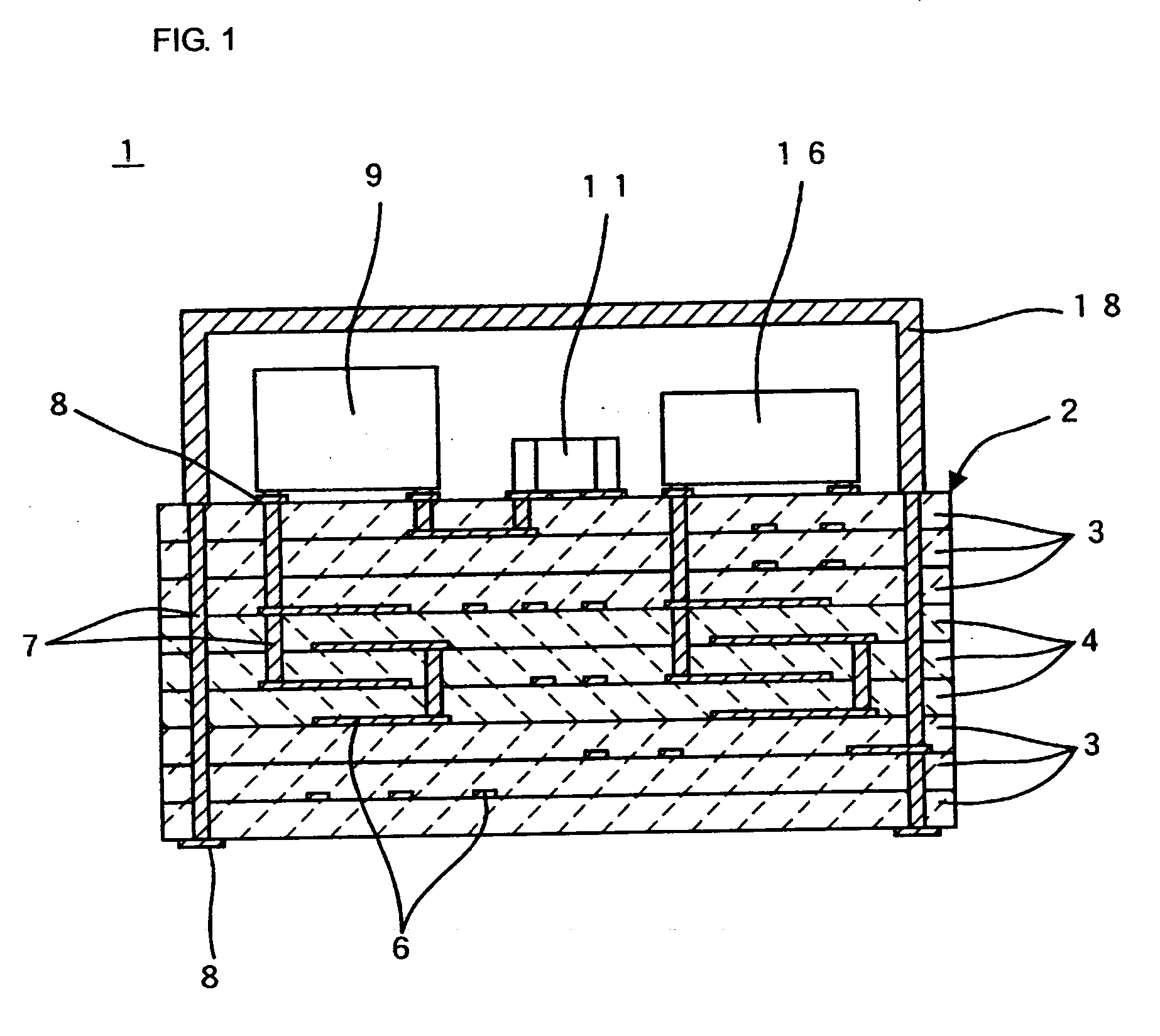
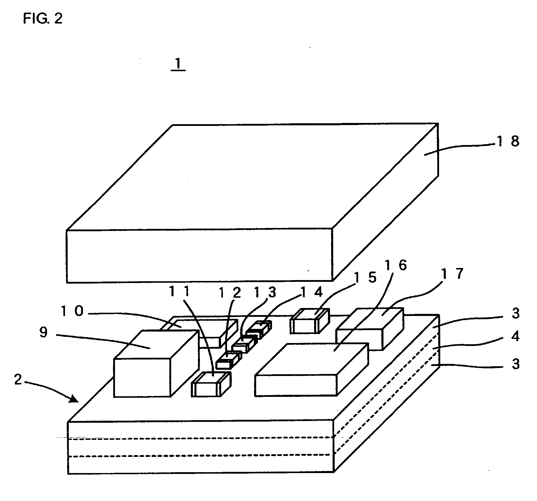
[0031] The insulating ceramic composition of the present invention contains a first ceramic powder mainly containing forsterite, a second ceramic powder essentially composed of at least one selected from the group consisting of a calcium titanate-based ceramic powder mainly containing calcium titanate, a strontium titanate-based ceramic powder mainly containing strontium titanate, and a titanium oxide-based ceramic powder mainly containing titanium oxide, and borosilicate glass powder having a specific composition. Consequently, the insulating ceramic composition can be fired at a temperature of 1000° C. or less, as will be clear from discussion below. The insulating ceramic sintered compact obtained by the firing is chemically stable and has a comparatively low relative dielectric constant and a high Qf value. The insulating ceramic sintered compact can also achieve a resonance frequency with a stable temperature coefficient (τf).
[0032] Accordingly, a monolithic ceramic electronic component made of the insulating ceramic sintered compact of the present invention allows the use of copper- or silver-based wiring conductors in the electronic component, and thus can be suitably used at high frequencies.
[0033] In the insulating ceramic composition of the present invention, the borosilicate glass content can be reduced to 20 percent by weight or less. Since borosilicate glass is relatively expensive, the reduction of the borosilicate glass powder content is advantageous in terms of cost. The reduction of the borosilicate glass powder content also makes it easy to control the reaction between the second ceramic powder acting as an additive and the glass and to control the τf value with the additive.
[0034] The insulating ceramic composition further containing a third ceramic powder essentially composed of at least one ceramic powder selected from the group consisting of a copper oxide-based ceramic powder mainly containing (CuO), an iron oxide-based ceramic powder mainly containing iron oxide (Fe2O3), and a manganese oxide-based ceramic powder mainly containing manganese oxide (MnO2) in the above-described proportion can certainly achieve a Qf value of 10000 GHz or more and a resonance frequency with a temperature coefficient (τf) within ±30 ppm·° C.−1.
[0035] If the monolithic ceramic electronic component of the present invention further includes highly dielectric ceramic layers stacked together with the insulating ceramic layers, having a relative dielectric constant of 15 or more, the monolithic ceramic electronic component can offer high performance and can be small.
[0036] The highly dielectric ceramic layers formed of either of the above-described high dielectric constant materials allow the thermal expansion coefficients between the insulating ceramic layers and the highly dielectric ceramic layers to be close. The insulating ceramic layers and highly dielectric ceramic layers can maintain a good state of their joining without producing relatively large stress after firing.

Problems solved by technology

The multilayer ceramic module thus can be small and multifunctional, and the use of the multilayer ceramic module can lead to downsized electronic apparatuses.

Method used


Image

  • Insulating ceramic composition, insulating ceramic sintered body, and multilayer ceramic electronic component
  • Insulating ceramic composition, insulating ceramic sintered body, and multilayer ceramic electronic component
  • Insulating ceramic composition, insulating ceramic sintered body, and multilayer ceramic electronic component

Examples


experimental example 1

[0135] First, various types of composition shown in Table 1 were prepared for use as the borosilicate glass powder contained in the insulating ceramic composition.

TABLE 1Glass codeLi2O (wt %)MgO (wt %)B2O3 (wt %)SiO2 (wt %)ZnO (wt %)Al2O3 (wt %)Remarks* G1 2.038.025.027.08.0— G23.538.025.025.58.0— G315.032.020.023.010.0—* G4 16.532.020.021.510.0—* G5 6.028.026.028.08.04.0 G66.030.026.028.08.04.0 G75.049.022.018.06.0—* G8 5.055.019.015.06.0—Vitrification impossible* G9 8.044.014.025.07.02.0Vitrification difficultG108.042.016.025.07.02.0G116.034.029.021.010.0—* G12 6.033.031.020.010.0—* G13 10.038.023.09.010.010.0Vitrification impossibleG1410.038.023.011.010.08.0G156.035.017.034.08.0—* G16 6.033.017.036.08.0—* G17 6.031.028.031.04.0—G186.031.026.031.06.0—G196.037.019.018.020.0—* G20 6.035.019.018.022.0—* G21 6.035.020.015.08.016.0G226.035.020.016.58.014.5G236.041.020.026.07.0—

[0136] In Table 1, the glass powders represented by glass codes marked with asterisks * have compositions ou...

experimental example 2

[0155] Various types of ceramic powder mainly containing forsterite, having MgO / SiO2 molar ratios, impurity contents, and average particle sizes (center particle size D50) shown in Table 4 were prepared as the first ceramic powder contained in the insulating ceramic composition.

[0156] The ceramic powder essentially composed of a first ceramic “F4” in Table 4 corresponds to the first ceramic powder used in Experimental Example 1. Impurity contents were measured by ICP (plasma emission spectrometry). The first ceramic powders contained the following impurities: Al2O3, B2O3, CaO, Fe2O3, MnO2, NiO, SnO2, SrO, ZnO, P2O5, TiO2, ZrO2, Li2O, Na2O, and / or K2O.

TABLE 4First ceramicMgO / SiO2ImpurityAveragecodemolar ratiocontent (wt %)grain size (μm)* F1 1.901.60.7F21.932.10.8F31.951.90.7F42.001.80.8F52.031.60.8* F6 2.062.00.7F71.993.20.7F82.004.50.7* F9 1.995.80.8* F10 2.011.81.2

[0157] In Table 4, the first ceramic powder represented by first ceramic codes marked with asterisks * have conditi...

experimental example 3

[0169] Various types of ceramic powder with an average particle size of 1.5 μm, mainly containing SrTiO3 having SrO / TiO2 molar ratios, impurity contents, specific surface areas, and integrated intensities shown in Table 7 were used as part of the second ceramic powder contained in the insulating ceramic composition. The impurity contents shown in Table 7 were measured by ICP (plasma emission spectrometry). The integrated intensity was obtained from the diffraction peak of SrTiO3 (222) by powder X-ray diffraction. The X-ray diffractometer used a Cu target at a tube voltage of 50 kV and a tube current of 250 mA, and the measurements were continuously performed at sampling width of 0.02°.

TABLE 7SpecificSecondSrO / TiO2ImpuritiessurfaceceramicmolarContentareaIntegratedcoderatioConstituent(wt %)(m2 / g)intensity* S1 1.07BaO, Fe2O3, Al2O30.154.52200 S21.05BaO, Fe2O3, Al2O30.154.52200 S31.02BaO, Fe2O3, Al2O30.154.52200 S40.96BaO, Fe2O3, Al2O30.154.52200 S50.92BaO, Fe2O3, Al2O30.154.52200* S6...


PUM

PropertyMeasurementUnit
molar ratioaaaaaaaaaa
particle size D50aaaaaaaaaa
molar ratioaaaaaaaaaa

Abstract

An insulating ceramic composition forming insulating ceramic layers (3) stacked in a multilayer ceramic substrate (2) used in a monolithic ceramic electronic component, such as a multilayer ceramic module (1). The insulating ceramic composition contains a first ceramic powder mainly containing forsterite, a second ceramic powder mainly containing at least one compound selected from the group consisting of CaTiO3, SrTiO3, and TiO2, and a borosilicate glass powder. The borosilicate glass powder contains 3 to 15 percent by weight of lithium in terms of Li2O, 30 to 50 percent by weight of magnesium in terms of MgO, 15 to 30 percent by weight of boron in terms of B2O3, 10 to 35 percent by weight of silicon in terms of SiO2, 6 to 20 percent by weight of zinc in terms of ZnO, and 0 to 15 percent by weight of aluminum in terms of Al2O3. The insulating ceramic composition can be fired at a temperature of 1000° C. or less, and the resulting sintered compact has a low relative dielectric constant, a resonance frequency with a low temperature coefficient, and a high Q value.

Description

TECHNICAL FIELD [0001] The present invention relates to insulating ceramic compositions, particularly an insulating ceramic composition containing a glass component so as to make it possible to be fired at low temperatures, to an insulating ceramic sintered compact prepared by firing the insulating ceramic composition, and to a monolithic ceramic electronic component using the insulating ceramic sintered compact. BACKGROUND ART [0002] One of the effective approaches for downsizing electronic apparatuses is to use multifunctional electronic components in the electronic apparatuses. Among the multifunctional electronic components are multilayer ceramic modules, for example. [0003] A multilayer ceramic module includes a multilayer ceramic substrate. The multilayer ceramic substrate contains wiring conductors for establishing electrical connections or forming passive elements, such as a capacitor and an inductor, inside. Also, various types of electronic components are disposed on the m...

Claims


Application Information

Patent Timeline
Patent Type & Authority Applications(United States)
IPC IPC(8): C03C14/00C04B35/468C04B35/20C04B35/462H01G4/12H01G4/30H05K1/03
CPCB32B2315/02Y10T428/24926C04B35/20C04B35/462C04B2235/3201C04B2235/3208C04B2235/3213C04B2235/3215C04B2235/3224C04B2235/3232C04B2235/3236C04B2235/3267C04B2235/3272C04B2235/3281C04B2235/3445C04B2235/365C04B2235/5409C04B2235/5436C04B2235/5445C04B2235/6025C04B2235/656C04B2235/72C04B2235/79C04B2237/341C04B2237/346H01G4/1218H01G4/129H01G4/30H05K1/0306C03C3/066H01L2224/16227H01L2224/16235H01L2924/15192H01L2924/15313H01L2924/16251H01L2924/19105H01L2924/3025C04B35/16
Inventor MORI, NAOYAURAKAWA, JUNSUGIMOTO, YASUTAKA
Owner MURATA MFG CO LTD
Why Eureka
Try Eureka