Resist protective coating material and patterning process

a technology of resist and coating material, applied in the direction of photosensitive materials, instruments, photomechanical equipment, etc., can solve the problems of low resist etch resistance, high cost of scanners, and increased cost of scanning, so as to achieve effective pattern formation and improve process compatibility

Active Publication Date: 2007-01-04
SHIN ETSU CHEM IND CO LTD
View PDF20 Cites 40 Cited by
  • Summary
  • Abstract
  • Description
  • Claims
  • Application Information

AI Technical Summary

Benefits of technology

[0011] An object of the invention is to provide a resist protective coating material which is best suited for the immersion lithography in that it enables effective pattern formation by the

Problems solved by technology

However, for the reasons that the projection lens uses a large amount of expensive CaF2 single crystal, the scanner thus becomes expensive, hard pellicles are introduced due to the extremely low durability of soft pellicles, the optical system must be accordingly altered, and the etch resistance of resist is low; the postponement of F2 lithography and the early introduction of ArF immersion lithography were advocated (see Proc.
Several problems associated with the presence of water on resist were pointed out.
As is well known in the art, the use of fluorocarbons now raises an issue from the standpoint of environmental protect

Method used


Image

  • Resist protective coating material and patterning process
  • Resist protective coating material and patterning process
  • Resist protective coating material and patterning process

Examples


synthesis example 1

[0043] A 200-ml flask was charged with 36 g of Monomer 1 and 40 g of methanol as a solvent. The reactor was subjected to cooling to −70° C. in a nitrogen atmosphere, evacuation to vacuum, and nitrogen flow, which procedure was repeated three times. The reactor was warmed up to room temperature, charged with 3 g of 2,2′-azobis(2,4-dimethylvaleronitrile) as a polymerization initiator, heated at 65° C., and held for 25 hours for reaction. The reaction solution was poured into hexane for crystallization whereupon the resin was isolated. The resin, designated Inventive Polymer 1, was analyzed for composition by 1H-NMR and for molecular weight by GPC.

synthesis example 2

[0044] A 200-ml flask was charged with 25.6 g of Monomer 1, 9 g of Monomer 3, and 40 g of methanol as a solvent. The reactor was subjected to cooling to −70° C. in a nitrogen atmosphere, evacuation to vacuum, and nitrogen flow, which procedure was repeated three times. The reactor was warmed up to room temperature, charged with 3 g of 2,2′-azobis(2,4-dimethylvaleronitrile) as a polymerization initiator, heated at 65° C., and held for 25 hours for reaction. The reaction solution was poured into hexane for crystallization whereupon the resin was isolated. The resin, designated Inventive Polymer 2, was analyzed for composition by 1H-NMR and for molecular weight by GPC.

synthesis example 3

[0045] A 200-ml flask was charged with 26.9 g of Monomer 2, 9 g of Monomer 3, and 40 g of methanol as a solvent. The reactor was subjected to cooling to −70° C. in a nitrogen atmosphere, evacuation to vacuum, and nitrogen flow, which procedure was repeated three times. The reactor was warmed up to room temperature, charged with 3 g of 2,2′-azobis(2,4-dimethylvaleronitrile) as a polymerization initiator, heated at 65° C., and held for 25 hours for reaction. The reaction solution was poured into hexane for crystallization whereupon the resin was isolated. The resin, designated Inventive Polymer 3, was analyzed for composition by 1H-NMR and for molecular weight by GPC.


PUM

PropertyMeasurementUnit
Wavelengthaaaaaaaaaa
Angleaaaaaaaaaa
Angleaaaaaaaaaa

Abstract

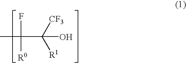
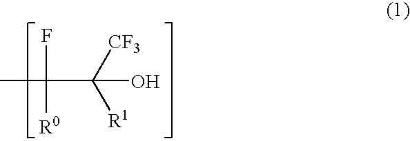
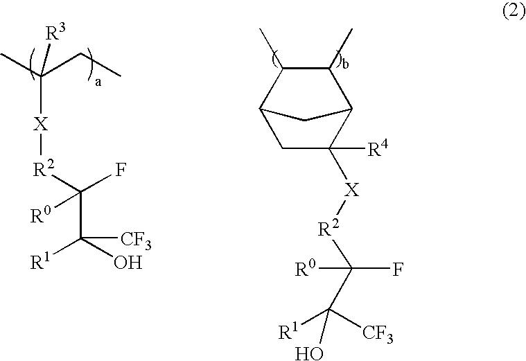
A resist protective coating material is provided comprising a polymer having a partial structure of formula (1) wherein R0 is H, F, alkyl or alkylene, and R1 is fluorinated alkyl or alkylene. In a pattern-forming process, the material forms on a resist film a protective coating which is water-insoluble, dissolvable in alkaline developer and immiscible with the resist film, allowing for effective implementation of immersion lithography. During alkali development, development of the resist film and removal of the protective coating can be simultaneously achieved.

Description

CROSS-REFERENCE TO RELATED APPLICATION [0001] This non-provisional application claims priority under 35 U.S.C. §119(a) on Patent Application No. 2005-174615 filed in Japan on Jun. 15, 2005, the entire contents of which are hereby incorporated by reference. TECHNICAL FIELD [0002] This invention generally relates to a micropatterning process for the fabrication of semiconductor devices, and particularly to an immersion lithography process involving directing ArF excimer laser radiation having a wavelength of 193 nm from a projection lens toward a wafer, with water intervening between the lens and the wafer. More particularly, it relates to a resist protective coating material used as a resist overlay for protecting photoresist and a process for forming a resist pattern using the same. BACKGROUND ART [0003] In the recent drive for higher integration and operating speeds in LSI devices, the pattern rule is made drastically finer. The photolithography which is currently on widespread use...

Claims


Application Information

Patent Timeline
IPC IPC(8): G03C1/00
CPCG03F7/0046G03F7/2041G03F7/11G03F7/70341
Inventor HATAKEYAMA, JUNWATANABE, TAKERUHARADA, YUJI
Owner SHIN ETSU CHEM IND CO LTD
Why Eureka
Try Eureka