Phosphor and light-emitting equipment using phosphor

a technology of phosphor and light-emitting equipment, which is applied in the field of phosphor, can solve the problems of phosphor exhibiting no decrease in luminance, unable to achieve the desired luminance reduction, and insufficient red color emission of luminance, etc., and achieve the effect of reducing luminan

Active Publication Date: 2007-01-11
NICHIA CORP +1
View PDF32 Cites 272 Cited by
  • Summary
  • Abstract
  • Description
  • Claims
  • Application Information

AI Technical Summary

Benefits of technology

[0037] The invention intends to reply such demands and an object thereof is to provide an inorganic phosphor which emits an orange or red light having a longer wavelength than that of conventional sialon phosphors activated with a rare earth, has a high luminance, and is chemically stable. Furthermore, another object of the invention is to provide a lighting equipment excellent in color-rendering properties, an image display unit excellent in durability, a pigment, and an ultraviolet absorbent using such a phosphor.
[0040] Furthermore, they have found that, among the above compositions, a solid solution crystal phase containing an inorganic compound having the same crystal structure as that of the CaAlSiN3 crystal phase as a host crystal and incorporated with an optically active element M, particularly Eu as an emission center forms a phosphor emitting an orange or red light having an especially high luminance. Furthermore, they have found that a white light-emitting diode which has a high emission efficiency, is rich in a red component, and exhibits good color-rendering properties can be obtained by using the phosphor.
[0087] The phosphor of the invention contains a multi-element nitride containing a divalent element, a trivalent element, and a tetravalent element, particularly a crystal phase represented by CaAlSiN3, another crystal phase having the same crystal structure as it, or a solid solution of these crystal phases as a main component and thereby exhibits light emission at a longer wavelength than that in the cases of conventional sialon and oxynitride phosphors, so that the phosphor of the invention is excellent as an orange or red phosphor. Even when exposed to an excitation source, the phosphor does not exhibit decrease of luminance and thus provides a useful phosphor which is suitably employed in VFD, FED, PDP, CRT, white LED, and the like. Moreover, among the phosphors, since the host of a specific inorganic compound has a red color and the compound absorbs an ultraviolet ray, it is suitable as a red pigment and an ultraviolet absorbent.

Problems solved by technology

However, as a result of exposure of the phosphors to the above excitation source, there arises a problem of decrease of luminance of the phosphors and hence a phosphor exhibiting no decrease of luminance has been desired.
The phosphors emitting a light of red color are also known but emitting luminance of red color is not sufficient by excitation with a blue visible light.
Moreover, they are chemically unstable in some composition and thus their durability is problematic.
However, there is a problem that the white light-emitting diode comprising a blue light-emitting diode element and the yttrium.aluminum.garnet-based phosphor has a characteristic of emitting a bluish-white light because of an insufficient red component and hence deflection is found in color-rendering properties.
However, a problem to be improved regarding color-rendering properties still remains also in these inventions, and hence it is desired to develop a light-emitting diode where the problem is solved, The red phosphor described in JP-A-10-163535 (Patent Literature 11) contains cadmium and thus there is a problem of environmental pollution.

Method used


Image

  • Phosphor and light-emitting equipment using phosphor
  • Phosphor and light-emitting equipment using phosphor
  • Phosphor and light-emitting equipment using phosphor

Examples


example 1

[0174] As raw powders were used a silicon nitride powder having an average particle size of 0.5 μm, an oxygen content of 0.93% by weight, and an α-type content of 92%, an aluminum nitride powder having a specific surface area of 3.3 m2 / g and an oxygen content of 0.79%, a calcium nitride powder, and europium nitride synthesized by nitriding metal europium in ammonia.

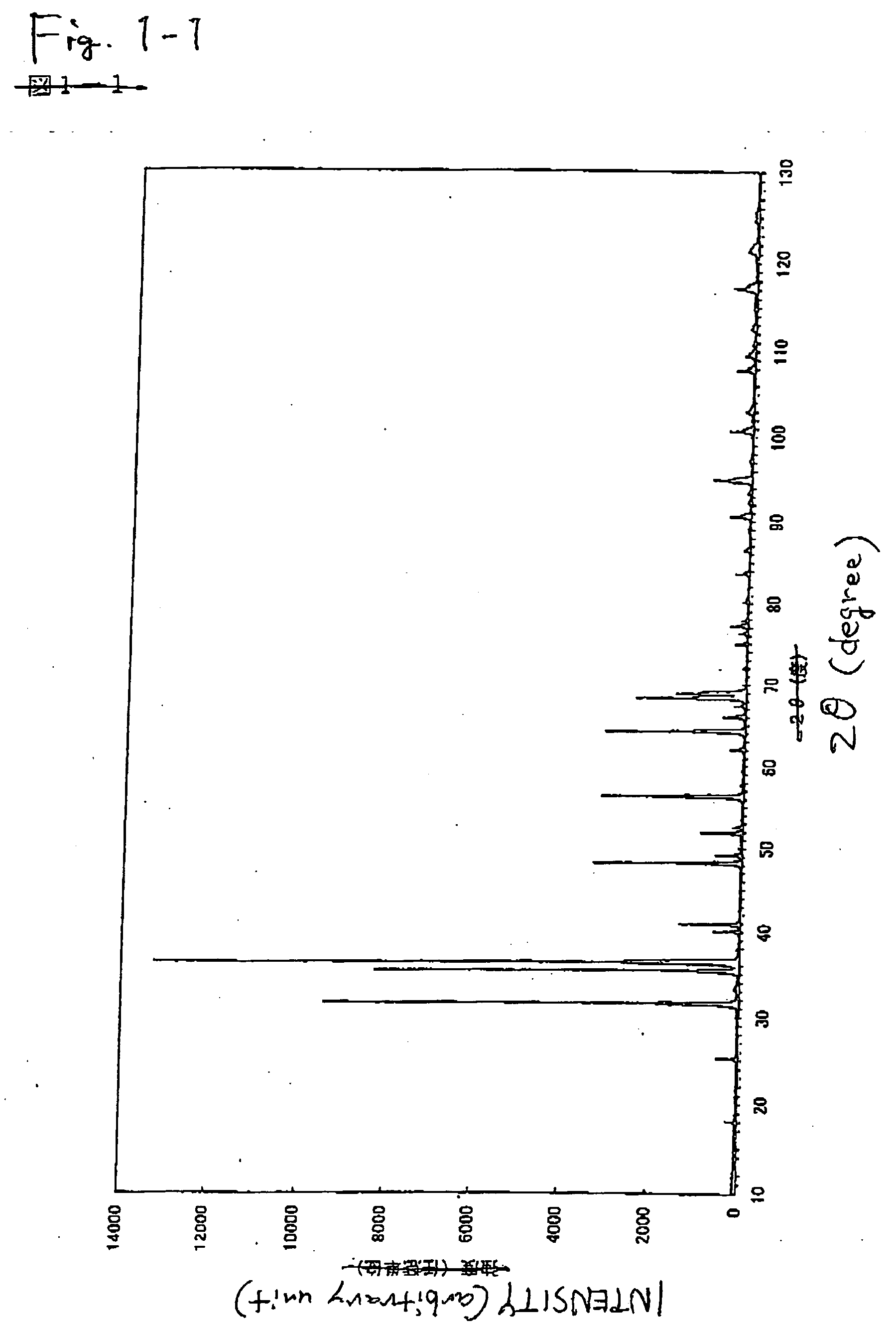
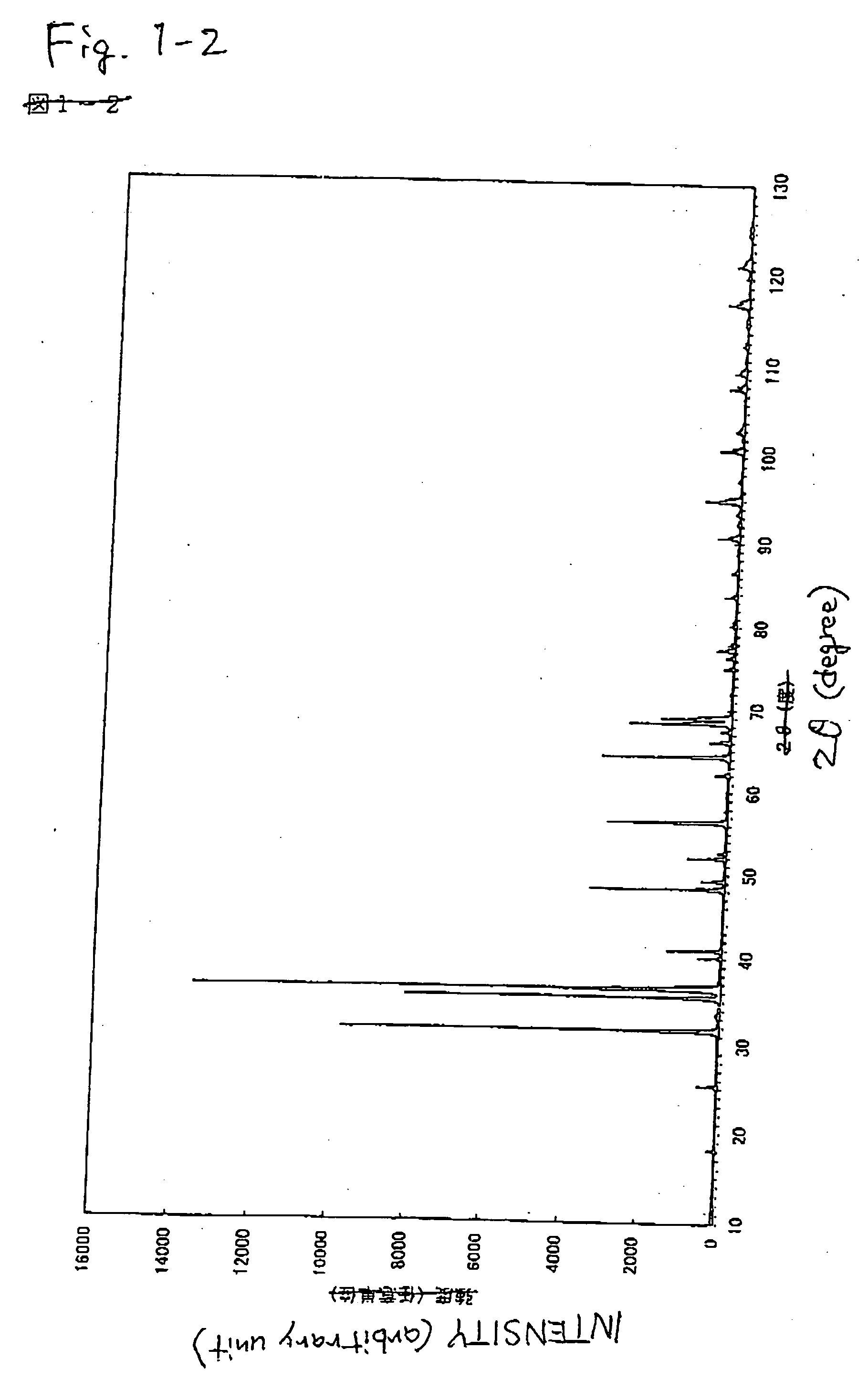
[0175] In order to obtain a compound represented by the composition formula: Eu0.008Ca0.992AlSiN3 (Table 1 shows parameters for designed composition, Table 2 shows designed composition (% by weight), and Table 3 shows a mixing composition of a raw powder), the silicon nitride powder, the aluminum nitride powder, the calcium nitride powder, and the europium nitride powder were weighed so as to be 33.8578% by weight, 29.6814% by weight, 35.4993% by weight, and 0.96147% by weight, respectively, followed by 30 minutes of mixing by means of an agate mortar and pestle. Thereafter, the resulting mixture was allowed to fall free...

examples 2 to 7

[0188] As Examples 2 to 7 were prepared inorganic compounds having a composition in which part or all of Ca was replaced with Ba.

[0189] The inorganic compounds were prepared in the same manner as in Example 1 with the exception of the compositions shown in Tables 1, 2, and 3. According to the measurement of X-ray diffraction, it was confirmed that the synthesized powders were inorganic compounds having the same crystal structure as that of CaAlSiN3. When excitation and emission spectra of the synthesized inorganic compound were measured, as shown in FIGS. 4 and 5, and Table 6, it was confirmed that they were red phosphors having an emission peak in the range of 570 nm to 700 nm, which were excited with an ultraviolet ray or a visible light of 350 nm to 600 nm. Incidentally, since emission luminance decreases as an added amount of Ba increases, a composition in the region where the added amount of Ba is small is preferred.

examples 8 to 15

[0190] As Examples 8 to 15 were prepared inorganic compounds having a composition in which part or all of Ca was replaced with Sr.

[0191] Phosphors were prepared in the same manner as in Example 1 with the exception of the compositions shown in Tables 1, 2, and 3. According to the measurement of X-ray diffraction, it was confirmed that the synthesized powders were inorganic compounds having the same crystal structure as that of CaAlSiN3. When excitation and emission spectra of the synthesized inorganic compound were measured, as shown in FIGS. 6 and 7 (Examples 8 to 11), FIGS. 8 and 9 (Examples 12 to 15), and Table 6, it was confirmed that they were red phosphors having an emission peak in the range of 570 nm to 700 nm, which were excited with an ultraviolet ray or a visible light of 350 nm to 600 nm. Incidentally, emission luminance decreases as an added amount of Sr increases, but the wavelength of the emission peak shifts to a shorter wavelength side as compared with the addition...


PUM


Abstract

An object of the present invention is to provide an inorganic phosphor having fluorescence properties emitting an orange or red light which has a longer wavelength as compared with the cases of conventional sialon phosphors activated with a rare earth. The invention relates to a design of white light-emitting diode rich in a red component and having good color-rendering properties by employing a solid solution crystal phase phosphor which uses as a host crystal an inorganic compound having the same crystal structure as that of a CaSiAlN3 crystal phase and to which M Element (wherein M Element is one or two or more elements selected from the group consisting of Mn, Ce, Pr, Nd, Sm, Eu, Tb, Dy, Ho, Er, Tm, and Yb) is added as an emission center.

Description

FIELD OF THE INVENTION [0001] The present invention relates to a phosphor mainly composed of an inorganic compound and applications thereof. More specifically, the applications relate to light-emitting equipments such as a lighting equipment and an image display unit as well as a pigment and an ultraviolet absorbent, which utilize a property possessed by the phosphor, i.e., a characteristic of emitting fluorescence having a long wavelength of 570 nm or longer. BACKGROUND ART [0002] Phosphors are used for a vacuum fluorescent display (VFD), a field emission display (FED), a plasma display panel (PDP), a cathode ray tube (CRT), a white light-emitting diode (LED), and the like. In all these applications, it is necessary to provide energy for exciting the phosphors in order to cause emission from the phosphors. The phosphors are excited by an excitation source having a high energy, such as a vacuum ultraviolet ray, an ultraviolet ray, an electron beam, or a blue light to emit a visible ...

Claims


Application Information

Patent Timeline
Patent Type & Authority Applications(United States)
IPC IPC(8): C09K11/08C01B21/06C01B21/082C04B35/58C04B35/581C04B35/584C04B35/597C09K3/00C09K11/64C09K11/66C09K11/67C09K11/77C09K11/80
CPCC01B21/0602C01B21/0821C01P2002/72C01P2002/77C01P2002/84C04B35/447C04B35/58C04B35/581C04B35/584C04B35/597C04B2235/3224C04B2235/3229C04B2235/3232C04B2235/3244C04B2235/3262C04B2235/3852C04B2235/3865C04B2235/3878C04B2235/3886C04B2235/445C04B2235/6567C04B2235/761C04B2235/77C09K11/0883C09K11/7734H01L33/502H01L2924/181H01L2224/48091H01L2224/48247H01L2224/73265C09K11/646C09K11/7764Y02B20/00C09K11/77498C09K11/77928C09K11/77218C09K11/77068C09K11/77348H01L2924/00014H01L2924/00012C09K11/55C09K11/59C09K11/643C09K11/7703C09K11/7718C09K11/7728C09K11/7746C09K11/7761C09K11/77748C09K11/7783
Inventor HIROSAKI, NAOTOUEDA, KYOTAYAMAMOTO, HAJIME
Owner NICHIA CORP
Why Eureka
Try Eureka