Fuel cell, fuel cell power source system and electronic devices using the same

a technology of power source system and fuel cell, which is applied in the direction of fuel cell details, cell components, electrochemical generators, etc., can solve the problems of unsuitable cell for size reduction, many problems remain in continuous operation of mobile electronic devices for long hours, and require charging equipment and a relatively long charging tim

Inactive Publication Date: 2007-02-15
HITACHI LTD
View PDF9 Cites 34 Cited by
  • Summary
  • Abstract
  • Description
  • Claims
  • Application Information

AI Technical Summary

Benefits of technology

[0015] According to the present invention, a carbon dioxide gas generated by the reaction of a cell is

Problems solved by technology

These secondary batteries however have to be charged after consumption of a predetermined volume of power, and they therefore require charging equipment and a relatively long charging time.
Thus, many problems have still remained in continuous operation of mobile electronic devices for long hours.
This cell is therefore unsuited for size reduction.
In the conventional DMFC, carbon dioxide generated in the reaction formula (1) and carbon monoxide which is an intermediate product accumulate in the anode electrode, anode diffusion layer or anode endplate and disturb the supply of fuel, which deteriorates a power generation efficiency, decreases an effective surface area of a catalyst to reduce an output voltage, and increases an internal pressure to disturb

Method used


Image

  • Fuel cell, fuel cell power source system and electronic devices using the same
  • Fuel cell, fuel cell power source system and electronic devices using the same
  • Fuel cell, fuel cell power source system and electronic devices using the same

Examples


example 1

(1) Synthesis of Chloromethylated Polyethersulfone

[0109] After a 500-ml four-necked round-bottom flask equipped with a stirrer, a thermometer, and a reflux condenser having a calcium chloride tube connected thereto was purged with nitrogen, 30 g of polyethersulfone (PES) and 250 ml of tetrachloroethane were charged in the flask, followed by the addition of 40 ml of chloromethyl methyl ether. A mixed solution of 1 ml of anhydrous tin chloride (IV) and 20 ml of tetrachloroethane was added dropwise. The reaction mixture was heated to 80° C. and stirred under heating for 90 minutes. The reaction mixture was charged in 1 liter of methanol to precipitate the corresponding polymer. The polymer thus precipitated was pulverized in a mixer and washed with methanol to yield chloromethylated polyethersulfone. The nuclear magnetic resonance spectrum of it revealed that the introduction ratio of a chloromethyl group {a ratio of a structural unit having a chloromethyl group introduced in it rela...

example 2

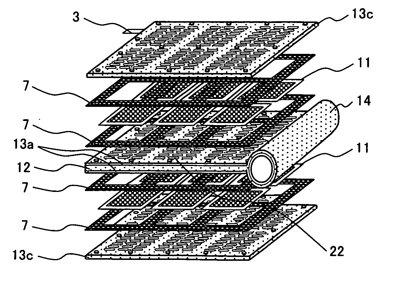
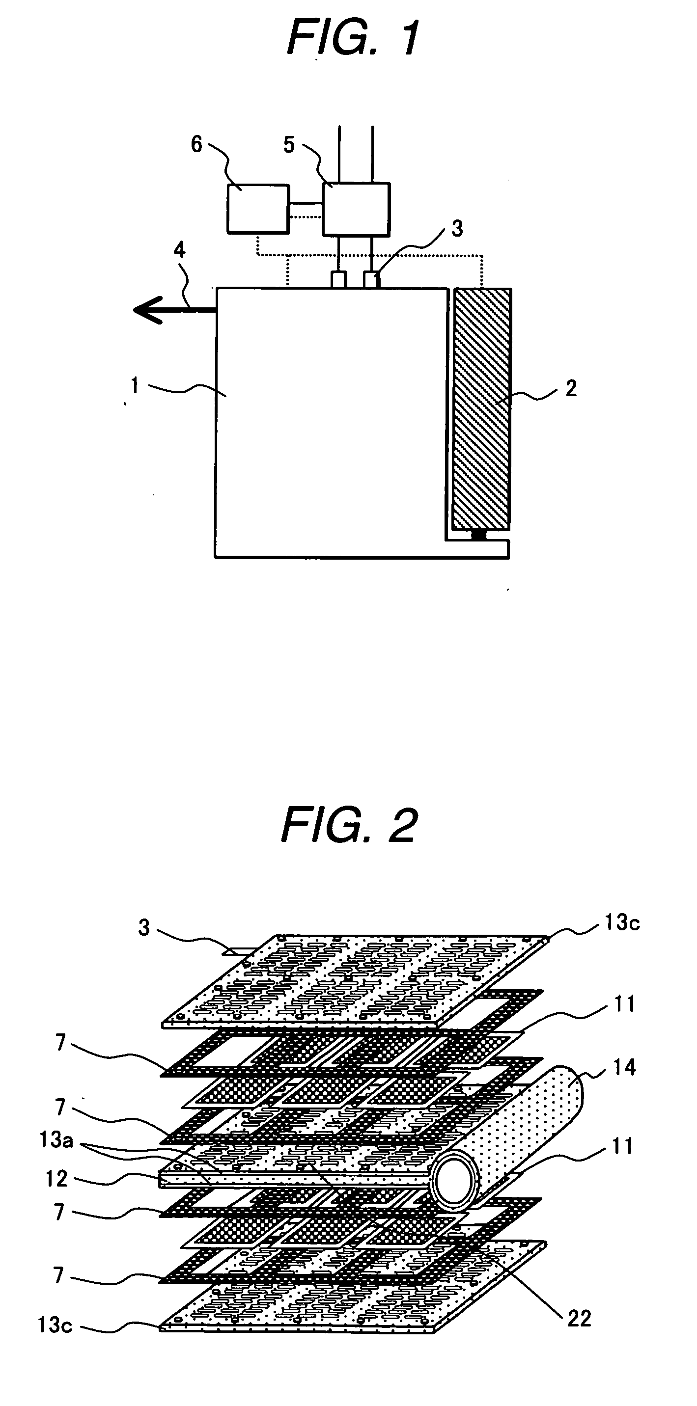
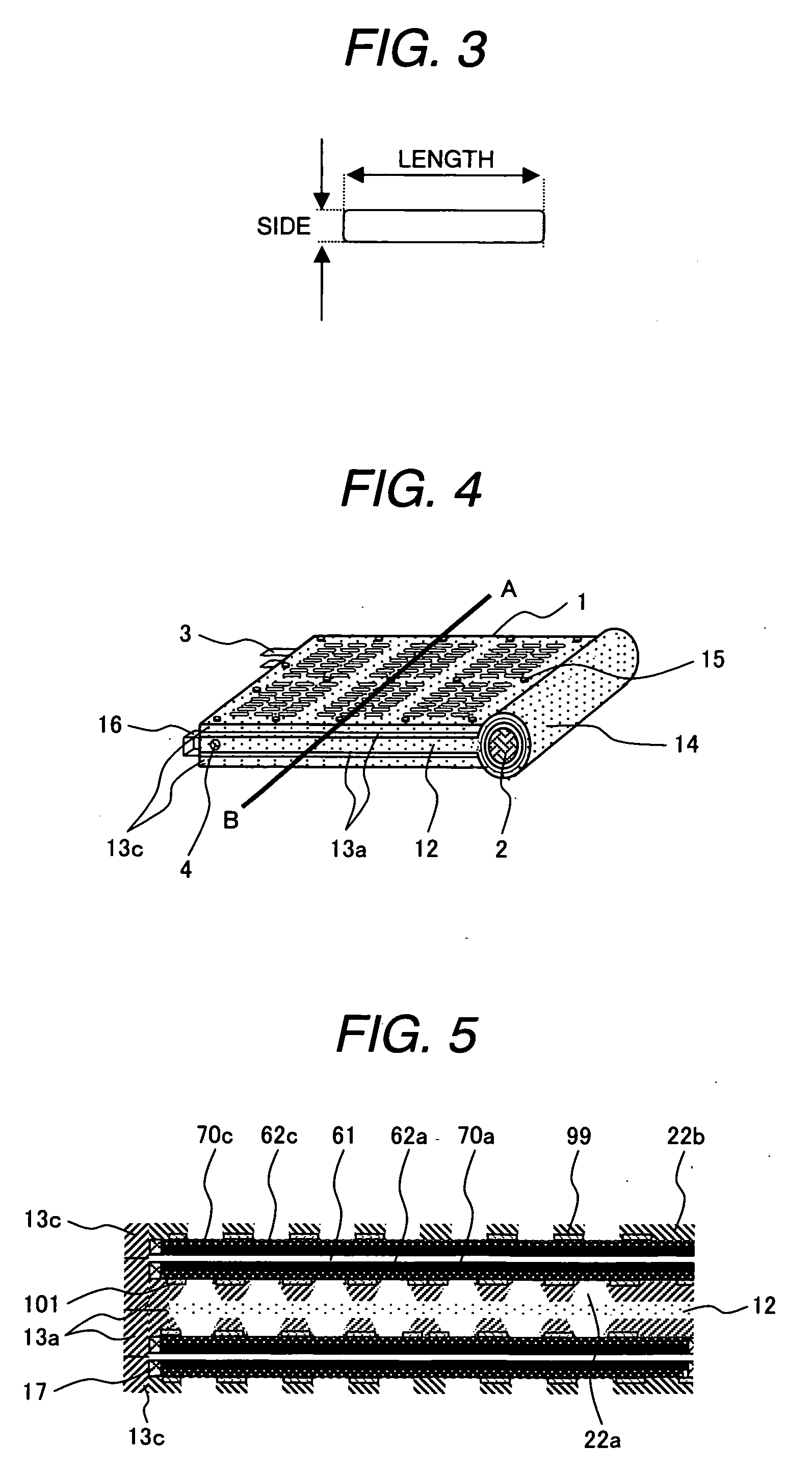
(1) Manufacture of Anode Endplate and Current Collector

[0133] Anode endplates and current collectors were manufactured by changing the short side / long side ratio of slits 122, 122a, 122b and 122c serving as transmission holes of fuel and carbon dioxide gas to 0.2, 0.36, 0.5, 0.8 and 1.0. The anode endplate and current collector were bonded and integrated by an epoxy resin. In addition, anode endplates and current collectors were manufactured by changing angles between the surface of the anode electrode and slits 122, 122a, 122b and 122c extending from the electrode toward the fuel tank to 90°, 85°, 80° and 70°, while fixing the short side / long side ratio to 0.36. The anode endplates and current collectors were bonded and integrated by an epoxy resin.

(2) Measurement of Contact Angle

[0134] The anode endplates integrated with the current collectors manufactured above in (1) were immersed in a 20 wt. % aqueous methanol solution contained in a Teflon (trade mark) vessel and the vess...

example 3

[0140] Anode endplates integrated with current collector subjected to UV / ozone treatment for 20 minutes, excimer laser treatment for 5 minutes, 10 minutes, 20 minutes or 30 minutes, or oxygen plasma treatment for 10 seconds were immersed in a 20 wt. % aqueous methanol solution contained in a Teflon (trade mark) vessel. The vessel was then put in an SUS pressure container. The pressure container was allowed to stand in a thermostat bath of 60° C. The anode endplates integrated with current collector were taken out after 2 days, 15 days and 60 days, respectively and wiped gently with “Kimwipe”. The contact angle with water was then measured using a contact angle meter “CA-D” (trade name) manufactured by Kyowa Interface Science. Results are shown in Tables 5 and 6. The anode endplates integrated with current collector subjected to UV / ozone treatment or oxygen plasma treatment had a contact angle of from 17 to 19°, while the anode endplates integrated with current collector subjected to...


PUM

PropertyMeasurementUnit
Temperatureaaaaaaaaaa

Abstract

Provided is a fuel cell having a membrane electrode assembly for generating power by oxidizing fuel at an anode electrode and reducing oxygen at a cathode electrode, an anode diffusion layer for allowing fuel to pass therethrough to the outside of the anode electrode of the membrane electrode assembly and transferring electrons generated by the oxidation, a cathode diffusion layer for removing water thus generated and transferring electrons to be used for the reduction to the lo outside of the cathode electrode, an anode current collector and anode endplate for transferring electrons generated by the oxidation to the outside of the anode diffusion layer, and a cathode current collector and a cathode endplate for transferring electrons to be used for the reduction to the outside of the cathode diffusion layer. The anode endplate or anode current collecting layer is hydrophilic or the end plate on the anode side has a constitution promoting discharge of a gas generated by the reaction.

Description

CLAIM OF PRIORITY [0001] This application claims priority from Japanese application serial No. 2005-230587, filed on Aug. 9, 2005, the content of which is hereby incorporated into this application. FIELD OF THE INVENTION [0002] The present invention relates to a fuel cell power source system composed of an anode, an electrolyte membrane, a cathode and a diffusion layer and carries out oxidation of fuel at the anode and reduction of oxygen at the cathode, particularly to a small-sized mobile fuel cell power source system using liquid fuel such as methanol, dimethyl ether or ethylene glycol and mobile electric or electronic devices using the system. BACKGROUND OF THE INVENTION [0003] With the recent development of electronic technologies, cellular phones, laptop personal computers, digital cameras, audio-visual equipment, personal digital assistants and the like have become compact, and have spread widely as mobile electronic devices. Such mobile electronic devices are conventionally ...

Claims


Application Information

Patent Timeline
IPC IPC(8): H01M4/94H01M8/02
CPCH01M8/0232H01M8/0234H01M8/0239H01M8/0245H01M8/0247Y02E60/523H01M8/04186H01M8/04208H01M8/1004H01M8/1011H01M8/1018H01M8/04171Y02E60/50
Inventor KOYAMA, TORUKUBOTA, OSAMUSASAKI, HIROSHISOUMA, KENICHI
Owner HITACHI LTD
Why Eureka
Try Eureka