

Negative electrode for lithium secondary cell, lithium secondary cell employing the negative electrode, film deposition material b used for forming negative electrode, and process for producing negative electrode
- Summary
- Abstract
- Description
- Claims
- Application Information
AI Technical Summary
Benefits of technology
Problems solved by technology
Method used
Image

Examples
first embodiment
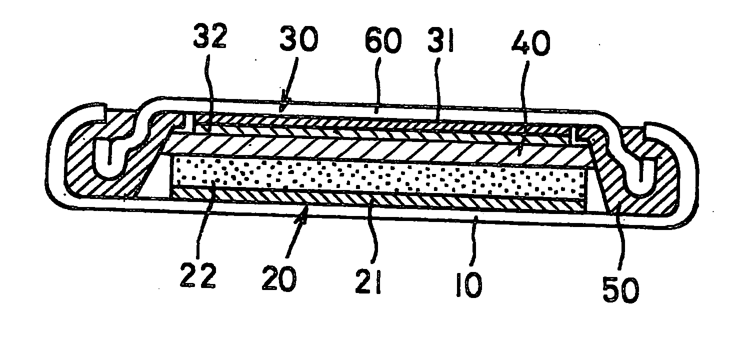
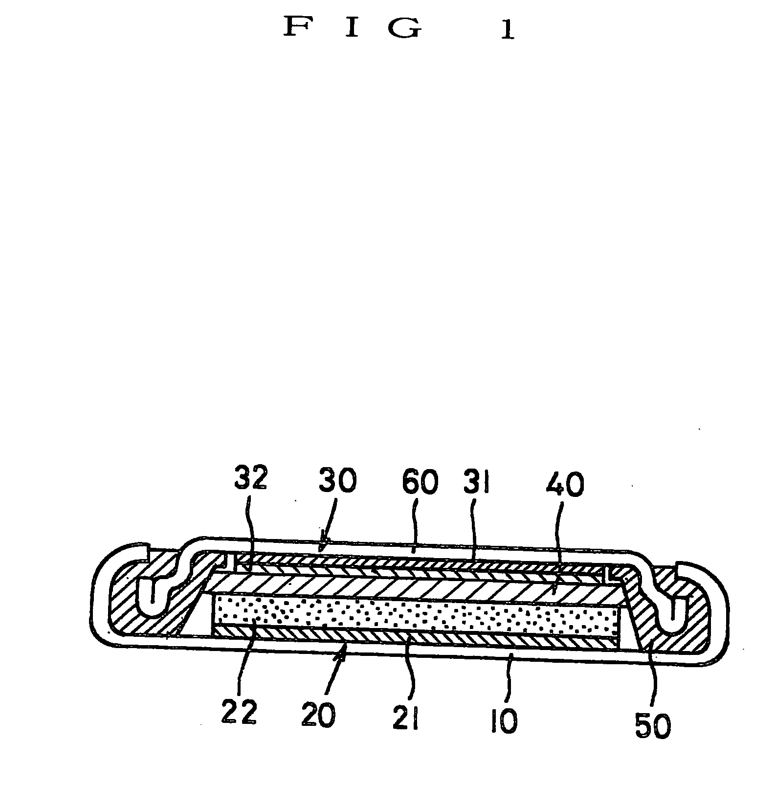
[0062] A lithium secondary battery of the first embodiment is a so-called button cell as shown in FIG. 1 and equipped with a circular flat case 10 forming a positive electrode face. The case 10 is made of a metal, and a positive electrode 20 and an negative electrode 30 are laminated in the order from below and accommodated inside thereof. The positive electrode 20 is constituted of a collector 21 made of a circular metal thin plate and a positive electrode active material layer 22 formed on the surface of the collector 21. Similarly, the negative electrode 30 is constituted of a collector 31 made of a circular metal thin plate and an negative electrode active material layer 32 formed on a surface of the collector 31. The active material layers of both electrodes are opposite each other and a separator 40 is sandwiched between opposing faces of the layers, the constituents of which are thus stacked, and the layered structure is accommodated in the case 10.
[0063] An electrolyte toge...
second embodiment
[0104] What attention should be paid to of a lithium secondary battery of the second embodiment is that an negative electrode active material layer 32 of an negative electrode 30 is comprising a dense thin film of SiO formed on a collector 31 with an SiO deposit as a film formation material by vacuum vapor deposition or sputtering, preferably ion plating, which is a kind of the vacuum vapor deposition. To be more concrete, the negative electrode active material layer 32 of the negative electrode 30 is a thin film made of an SiO deposit with a weight decrease percent (a rattler value) in a rattler test of 1.0% or less. A thickness of the thin film is appropriately in the range of 0.1 to 50 μm.
[0105] On the other hand, a positive electrode active material 22 of a positive electrode 20 is prepared in a conventional procedure according to a powder kneaded coated dried method in which powder of oxide of a transition metal containing lithium such as LiCoO2 is mixed into a binder solution...
third embodiment
[0114] What attention should be paid to about a lithium secondary battery of the third embodiment is that an negative electrode active material layer 32 of an negative electrode 30 is constituted of a dense thin layer of SiO formed on a collector 31 by vacuum vapor deposition, or sputtering, preferably ion plating, which is a kind of the vacuum vapor deposition, with an SiO deposit as a film formation material.
[0115] To be more concrete, an SiO film is formed on a surface of a collector 31 by not only applying a cleaning treatment to a surface of the collector 31 by surface treatment bombardment with direct current magnetron discharge in a vacuum chamber but also, directly subsequent thereto, applying ion plating to the surface of the collector 31 in the vacuum chamber without exposing to an air atmosphere. A thickness of the SiO film is appropriately in the range of from 0.1 to 50 μm.
[0116] On the other hand, a positive electrode active material layer 22 of a positive electrode 2...
PUM
| Property | Measurement | Unit |
|---|---|---|
| Temperature | aaaaa | aaaaa |
| Fraction | aaaaa | aaaaa |
| Fraction | aaaaa | aaaaa |
Abstract
Description
Claims
Application Information