Optical element, light condensation backlight system, and liquid crystal display

a backlight system and liquid crystal display technology, applied in the field of optical elements, light condensation backlight systems, liquid crystal displays, can solve the problems of high cost, high technical difficulty, and difficult fabrication of such elements, and achieve good shielding direction effect, no absorption loss, and high transmittance.

Inactive Publication Date: 2007-03-22
NITTO DENKO CORP
View PDF0 Cites 18 Cited by
  • Summary
  • Abstract
  • Description
  • Claims
  • Application Information

AI Technical Summary

Benefits of technology

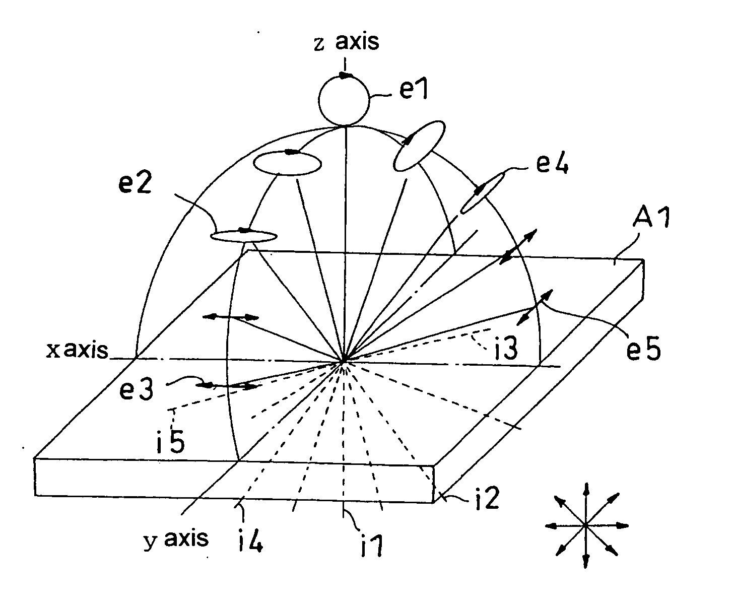
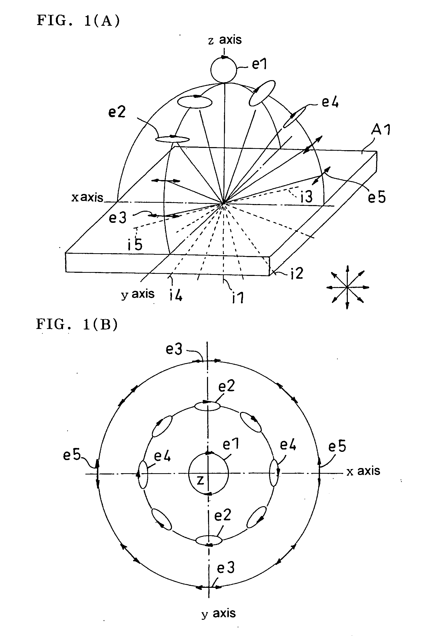
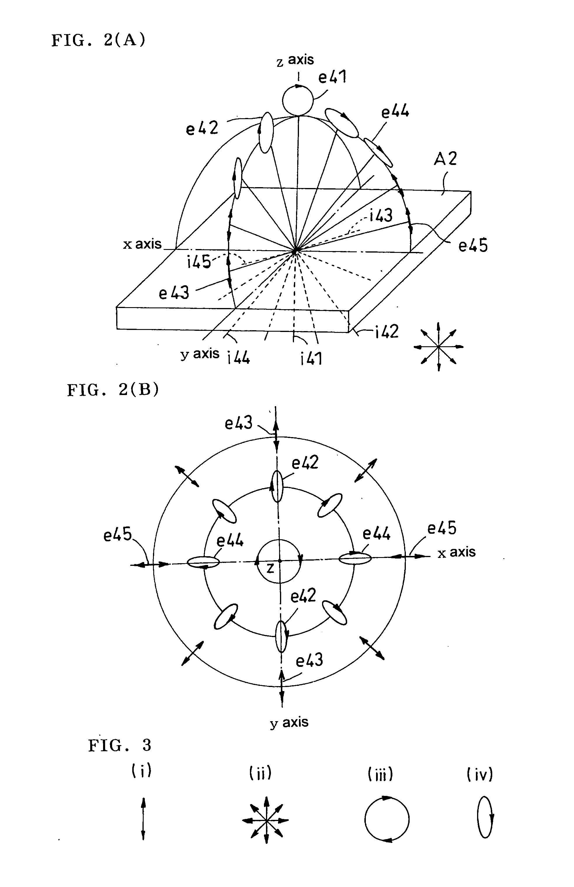
[0108] According to the invention, a characteristic that have been unable to be acquired from a conventional optical element can be easily realized. The use of an optical element of the invention makes it possible to obtain an optical element having a high transmittance in the front direction and a good shielding direction effect in an oblique direction, and having no absorption loss together with a selective reflection characteristic of a cholesteric liquid crystal. Precise adjustment on secondary transmission in an oblique direction and a wavelength characteristic is unnecessary to thereby enable a stable performance to be attained.
[0109] Since an optical element of the present invention does not require an air interface, which is dissimilar to cases of a conventional lens sheet or a prism sheet, it can be used as a laminate in single piece obtained by adhering itself to a polarizing plate, and is also useful in handleability. A great effect is exerted in realizing a thin type. Since the optical element has no regularity structure visually recognizable as in a prism structure, a moiré or the like is hard to occur and has advantages in removal of a diffusing plate or the like decreasing a total light transmittance, or realization of low haze (a total light transmittance is generally increased) with ease. It is naturally not problematical to use the optical element together with a prism sheet or the like. For example, a steep condensation on to the front is performed with a prism sheet or the like, wherein a secondary transmission peak caused by the prism sheet at a large emission angle can be preferably shielded with an optical element of this invention used in combination.
[0110] In a conventional backlight device using only a prism sheet, a direction of emission light peak has a tendency that the direction of emission light peak moves away from a light source cold cathode fluorescent lamp. This is because more of light emitted from a light guide plate in an oblique direction is emitted in a direction moving away from the light source cold cathode fluorescent lamp and it is difficult to position peak intensity in the normal direction to the screen. In contrast thereto, by using an optical element according to the present invention, an emission peak is enabled to coincide with the front direction with ease.
[0111] A combination of a light condensation backlight source using the optical element and a diffusing plate low in backscattering and generating no cancellation of polarization enables construction of a viewing angle magnification system to be built.
[0112] A light condensation backlight system using the optical element having been obtained in this way easily provides a light source higher in light collimation as compared with a conventional practice. Since, in addition, light collimation due to reflective polarization essentially having no absorption loss can be obtained, a reflected non-collimated light component is returned back to the backlight side and recycling during which only a collimated light component is extracted by scattering reflection is repeated, thereby enabling substantially high transmittance and substantially high light utilization efficiency to be obtained.

Problems solved by technology

In a method in which a bright line spectrum is used as an optical film imparting directivity to a diffusion light source, however, since a requirement is a high precision level related to wavelength matching between a kind of a light source and a band pass filter, which has made fabrication thereof difficult.
Therefore, in combination of a bright line light source and a band pass filter, a requirement is a precise matching of a wavelength of the light source with a band pass filter, which is high in technical difficulty.
This has led to complexity in construction and a high cost.
In this method, however, in a case where a condition that total reflection occurs at a specific angle is set, a problem has been remained that a transmission region emerges at an incidence angle larger than the specific angle.
Therefore, if a transmission characteristic is confined only in the front direction, a transmission component is, to the contrary, generated in an oblique direction, which has become a trouble.
In a general polarizer using a laminate of a chiral material and a retardation plate such as quartz crystal and saccharose, it is difficult to fabricate the rotatory polarizer, while intentionally controlling a retardation plate having a rotatory polarization characteristic changed by an incidence angle.
On the other hand, hologram materials are, in more of cases, expensive, poor in mechanical characteristics, and soft and weak in nature, which have been problematic about long term durability.
As discussed above, conventional optical elements have been problematic because of difficulty in fabrication, hardness in obtaining a target optical characteristic, poor reliability and the like.

Method used


Image

  • Optical element, light condensation backlight system, and liquid crystal display
  • Optical element, light condensation backlight system, and liquid crystal display
  • Optical element, light condensation backlight system, and liquid crystal display

Examples


example 1

(Polarizing Element (A))

[0242] Six kinds of cholesteric liquid crystal polymers with selective reflection central wavelengths of 420 nm, 460 nm, 510 nm, 580 nm, 660 nm and 710 nm were prepared based on the specification of EP No. 0834754 A1.

[0243] A cholesteric polymer was manufactured with a polymerizable nematic liquid crystal monomer A expressed by the following chemical structure 2:

and a polymerizable chiral agent B expressed by the following chemical structure 3 in the following proportions (in wt ratios)

[0244] selective reflection central wavelength: monomer A / chiral agent B (mixing ratio): selective reflection wavelength band (nm)

420 nm:  8 / 1430 to 460 nm460 nm: 9.2 / 1430 to 490 nm510 nm:10.7 / 1480 to 550 nm580 nm:12.8 / 1540 to 620 nm660 nm:14.7 / 1620 to 810 nm710 nm:  16 / 1660 to 880 nm

[0245] The liquid crystal mixture was dissolved into tetrahydrofuran to obtain a 33% solution, thereafter, the solution was purged with nitrogen in a circumstance at 60° C., then, a react...

example 2

(Polarizing Element (A))

[0258] A laminate made from cholesteric liquid crystals were obtained in a similar way to that in Example 1 with the exception that in Example 1, a polymerizable nematic liquid crystal monomer A and a polymerizable chiral agent B were used in the proportions (wt ratio) described below:

[0259] Selective reflection central wavelength: monomer A / chiral agent B (mixing ratio): selective reflection wavelength band (nm)

420 nm:  8 / 1400 to 460 nm460 nm: 9.2 / 1430 to 490 nm510 nm:10.7 / 1480 to 550 nm580 nm:12.8 / 1540 to 620 nm620 nm:  14 / 1580 to 750 nm

[0260] The laminate of the obtained cholesteric liquid crystals had a selective reflection function in the wavelength range of from 400 to 750 run. The laminate was indicated with (A1-2).

[0261] The polarizing element (A1-2) had a distortion rate in the front direction of about 0.65 and a distortion rate in a 60 degree oblique direction of about 0.03. Emitting light transmitted through the polarizing element (A1-2) was ...

example 3

(Polarizing Element (A))

[0264] A laminate made from cholesteric liquid crystals were obtained in a similar way to that in Example 1 with the exception that in Example 1, a polymerizable nematic liquid crystal monomer A and a polymerizable chiral agent B were used in the proportions (wt ratio) described below:

[0265] Selective reflection central wavelength: monomer A / chiral agent B (mixing ratio): selective reflection wavelength band (nm)

390 nm:  7 / 1400 to 460nm460 nm: 9.2 / 1430 to 490nm510 nm:10.7 / 1480 to 550nm580 nm:12.8 / 1540 to 620nm660 nm:14.7 / 1620 to 810nm850 nm:  20 / 1700 to 1000nm

[0266] The laminate of the obtained cholesteric liquid crystals had a selective reflection function in the wavelength range of from 400 to 1000 μm. The laminate was indicated with (A1-3).

[0267] The polarizing element (A1-3) had a distortion rate in the front direction of about 0.68 and a distortion rate in a 60 degree oblique direction of about 0.03. Emitting light transmitted through the polarizin...


PUM

PropertyMeasurementUnit
angleaaaaaaaaaa
thicknessaaaaaaaaaa
reflection band widthaaaaaaaaaa

Abstract

An optical element comprising: a polarizing element (A), separating incident light into polarization to then emit light, and made of a cholesteric liquid crystal, wherein the polarizing element (A) has a distortion rate with respect to emitting light to incident light in the normal direction of 0.5 or more and a distortion rate with respect to emitting light to incident light at an angle inclined from the normal direction by 60 degrees or more of 0.2 or less, the polarizing element (A) has a function increasing a linearly polarized light component of emitting light as incidence angle is larger; a ½ wavelength plate (B); a retardation layer (C) giving almost zero retardation to incident light in the front direction (normal direction) and giving a retardation to incident light in a direction inclined from the normal direction; and a ¼ wavelength plate (D); being arranged in this order, and further a linearly polarized light reflection polarizer (E), transmitting linearly polarized light with one polarization axis and selectively reflecting linearly polarized light with the other polarization axis perpendicular to the one polarization axis, is arranged on the ¼ wavelength plate (D) so that the transmission axis of the linearly polarized light reflection polarizer (E) and an axis of the transmitted light, which is transmitted through the polarizing element (A) to the ¼ wavelength plate (D) in this order, are the same direction. The optical element is capable of condensation and collimation of incident light from a light source and capable of suppressing transmission of light in an arbitrary direction.

Description

TECHNICAL FIELD [0001] The present invention relates to an optical element using a polarizing element. This invention further relates to a light condensation backlight system using the optical element and still further to a liquid crystal display using the same. BACKGROUND ART [0002] There has been conventionally conducted a trial to condense or collimate light from a diffusion light source using an optical film having a flat front surface or to control a transmittance of light therefrom in a specific direction of the optical film having a flat front surface. A typical example of such a trial is a method in which a bright line light source is combined with a band pass filter (see, for example, a publication of JP-A No. 6-235900, a publication of JP-A No. 2-158289, a publication of JP-A No. 10-321025, a specification of U.S. Pat. No. 6,307,604, a specification of DE 3836955 A, a specification of DE 422028 A, a specification of EP 578302 A, a specification of US 2002 / 34009 A and a pam...

Claims


Application Information

Patent Timeline
Patent Type & Authority Applications(United States)
IPC IPC(8): G02F1/1333F21S2/00G02B5/30F21S8/04F21V8/00F21Y103/00G02B27/28G02F1/13357
CPCG02B27/28G02B6/0056
Inventor SHIRAOGAWA, MIKITAKEDA, KENTAROUHARA, KAZUTAKATAKAHASHI, NAOKI
Owner NITTO DENKO CORP
Why Eureka
Try Eureka