Eureka AIR delivers breakthrough ideas for toughest innovation challenges, trusted by R&D personnel around the world.

Optical information recording medium and method for manufacturing the same

Inactive Publication Date: 2007-03-22
PANASONIC CORP
View PDF15 Cites 6 Cited by
  • Summary
  • Abstract
  • Description
  • Claims
  • Application Information

AI Technical Summary

Benefits of technology

[0014] It is an object of the present invention to solve the above problems and provide a recording medium that has high reliability and affords good recording and reproduction characteristics over a wide linear velocity range and high density, as well as a method for manufacturing this recording medium.

Problems solved by technology

With a multilayer recording medium such as this, the information layers on the side closer to the laser light source absorb light, so recording and reproduction are performed with attenuated laser light in the information layers on the side farther from the laser light source, so decreased sensitivity is a problem during recording, as are decreased reflectance and amplitude during reproduction.
For a medium to handle high-speed recording, a recording layer with a high crystallization rate has to be used as discussed above, but when such a layer is used for recording at low speed, the crystallization rate is too high.
That is, the problem is that amorphitization tends not to occur, and the marks tend not to be large enough, so there is a decrease in signal amplitude.
A thin film of silver alone is prone to corrosion, however, so other elements are usually added, and numerous alloys have been proposed.
However, the larger the amount in which these are added, the lower the thermal conductivity, so it is preferable for the added amount to be as small as possible, but on the other hand a smaller added amount means the alloy will be more susceptible to corrosion.
Furthermore, atom diffusion between adjacent layers can prevent the material from functioning as a recording medium, and this problem is particularly likely to occur in such cases as when the above-mentioned optical absorption layer is provided.

Method used


Image

  • Optical information recording medium and method for manufacturing the same
  • Optical information recording medium and method for manufacturing the same
  • Optical information recording medium and method for manufacturing the same

Examples


first embodiment

[0062] Embodiments of the present invention will now be described in specific terms through reference to the drawings.

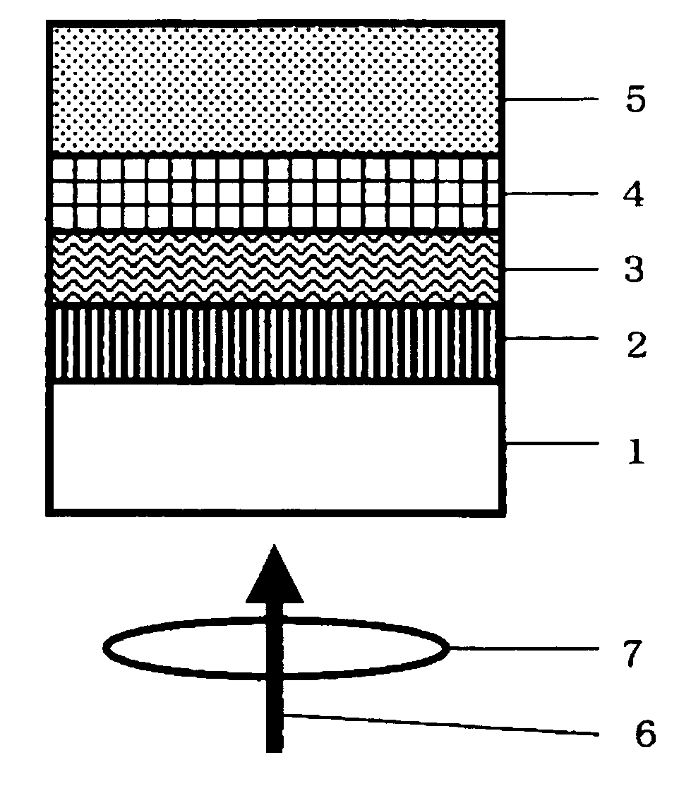
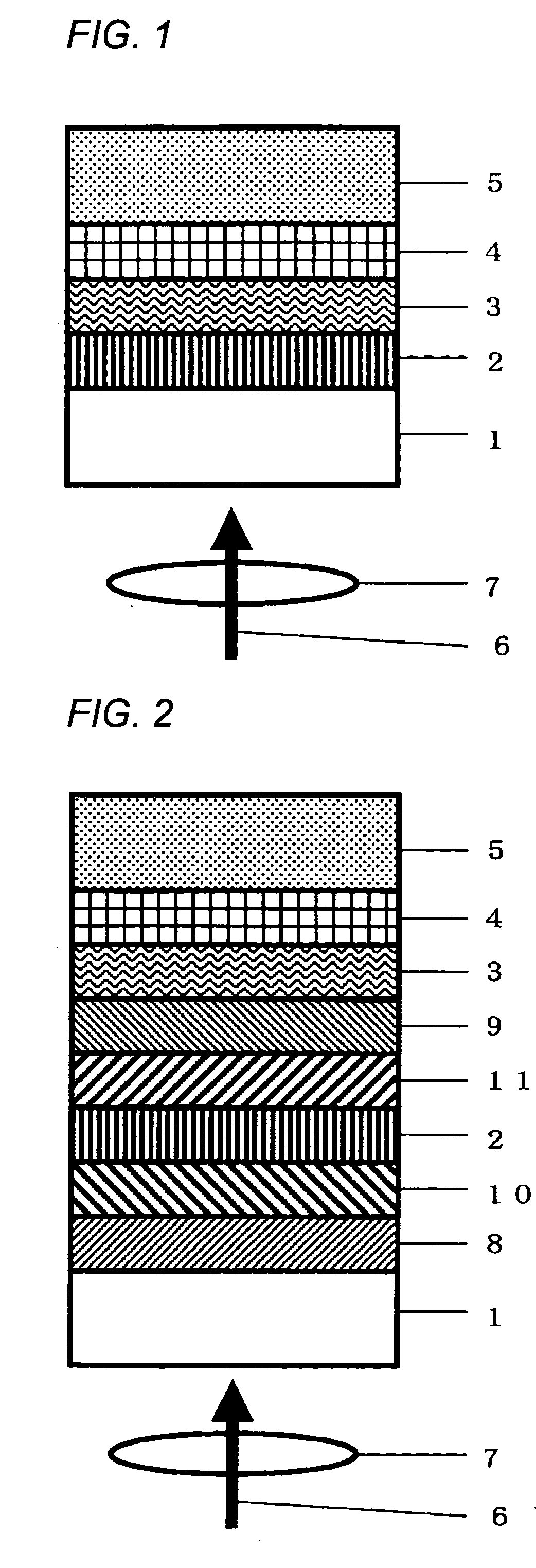
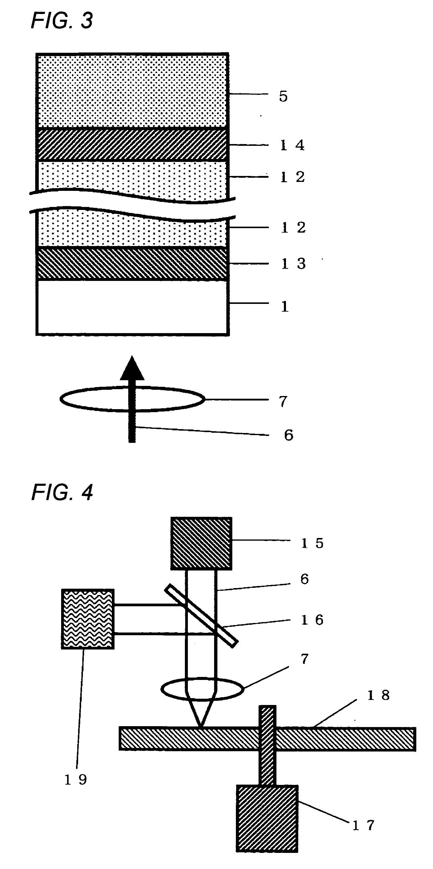
[0063] FIGS. 1 to 3 are partial cross-sectional diagrams of examples of the structure of the optical information recording medium of the present invention.

[0064] As shown in FIG. 1, in a optical information recording medium of the present invention, at least a recording layer 2, an optical absorption layer 3, a reflective layer 4, and a protective layer 5 are provided in that order on a transparent substrate 1. Recording and reproduction are performed with this optical information recording medium by converging laser light 6 with an objective lens 7 and irradiating the medium from the transparent substrate 1 side.

[0065] As shown in FIG. 2, a lower dielectric layer 8 may be provided between the transparent substrate 1 and the recording layer 2, an upper dielectric layer 9 may be provided between the recording layer 2 and the optical absorption layer 3, a lower inte...

example 1

[0089] A piece of polycarbonate resin, with a diameter of 12 cm, a thickness of 0.6 mm, a groove pitch of 1.23 μm, and a groove depth of approximately 55 nm was readied as a transparent substrate. A lower dielectric layer with a thickness of 120 nm and composed of (ZnS)80(SiO2)20, a lower interface layer with a thickness of 5 nm and composed of (ZrO2)46(Y2O3)4(Cr2O3O)50, a recording layer with a thickness of 8.5 nm and composed of Ge40Sb4Bi4Te52, an upper interface layer with a thickness of 5 nm and composed of (ZrO2)46(Y2O3)4(Cr2O3O)50, an upper dielectric layer with a thickness of 40 nm and composed of (ZnS)80(SiO2)20, an optical absorption layer with a thickness of 30 nm and composed of CrSi2, and a reflective layer with a thickness of 100 nm and composed of Ag98In2 were provided in that order on the surface of this transparent substrate where the grooves were formed, with these layers being formed by sputtering in an argon atmosphere. A protective substrate composed of polycarbo...


PUM


Abstract

The present invention provides a recording medium that has high reliability and affords good recording and reproduction characteristics over a wide linear velocity range and high density, as well as a method for manufacturing the recording medium. To this end, an optical information recording medium comprises at least a recording layer that changes its state to be different and optically detectable by irradiating with a light beam, an optical absorption layer composed of a material containing at least 50 at % and no more than 95 at % silicon, and a reflective layer composed of a material containing at least 95 at % silver and no more than 5 at % indium, with these layers provided in that order on a transparent substrate.

Description

TECHNICAL FIELD [0001] The present invention relates to an optical information recording medium and a method for manufacturing the recording medium, and more particularly relates to an optical information recording medium with which information signals can be recorded and reproduced by irradiation with a laser or the like, and to a method for manufacturing the recording medium. BACKGROUND ART [0002] If a thin film of a chalcogen material or the like formed on a substrate is locally heated by irradiation with laser light under different irradiation conditions, it is possible to cause the heated portion to undergo phase change between an amorphous phase and a crystalline phase with different optical constants (refractive index n and attenuation coefficient k). A great deal of research and development have gone into what are known as phase-change optical information recording media, in which this phenomenon is employed. [0003] With a phase-change optical information recording medium, i...

Claims


Application Information

Patent Timeline
IPC IPC(8): G03C5/00B32B3/02G11B7/24G11B7/24038G11B7/24067G11B7/243G11B7/2433G11B7/2531G11B7/2533G11B7/2534G11B7/254G11B7/257G11B7/2578G11B7/258G11B7/2585G11B7/259
CPCG11B7/24067G11B7/252G11B7/2531G11B7/2533G11B7/2534G11B2007/25715G11B7/2578G11B7/259G11B2007/25706G11B2007/25708G11B2007/2571G11B7/254
Inventor KITAURA, HIDEKIKOJIMA, RIE
Owner PANASONIC CORP
Why Eureka
Eureka Blog
Learn More