
Method and Device for High Density Optical Disk Data Storage

a high density, optical disk technology, applied in the direction of optical recording/reproducing/erasing methods, instruments, holographic processes, etc., can solve the problems of high density drives no longer removable, hard to achieve high density storage, and traditional magnetic disk storage has now reached its performance limitations, etc., to achieve fast access rate and high storage density

Inactive Publication Date: 2007-04-19
NEW SPAN OPTO TECH
View PDF9 Cites 12 Cited by
  • Summary
  • Abstract
  • Description
  • Claims
  • Application Information

AI Technical Summary

Benefits of technology

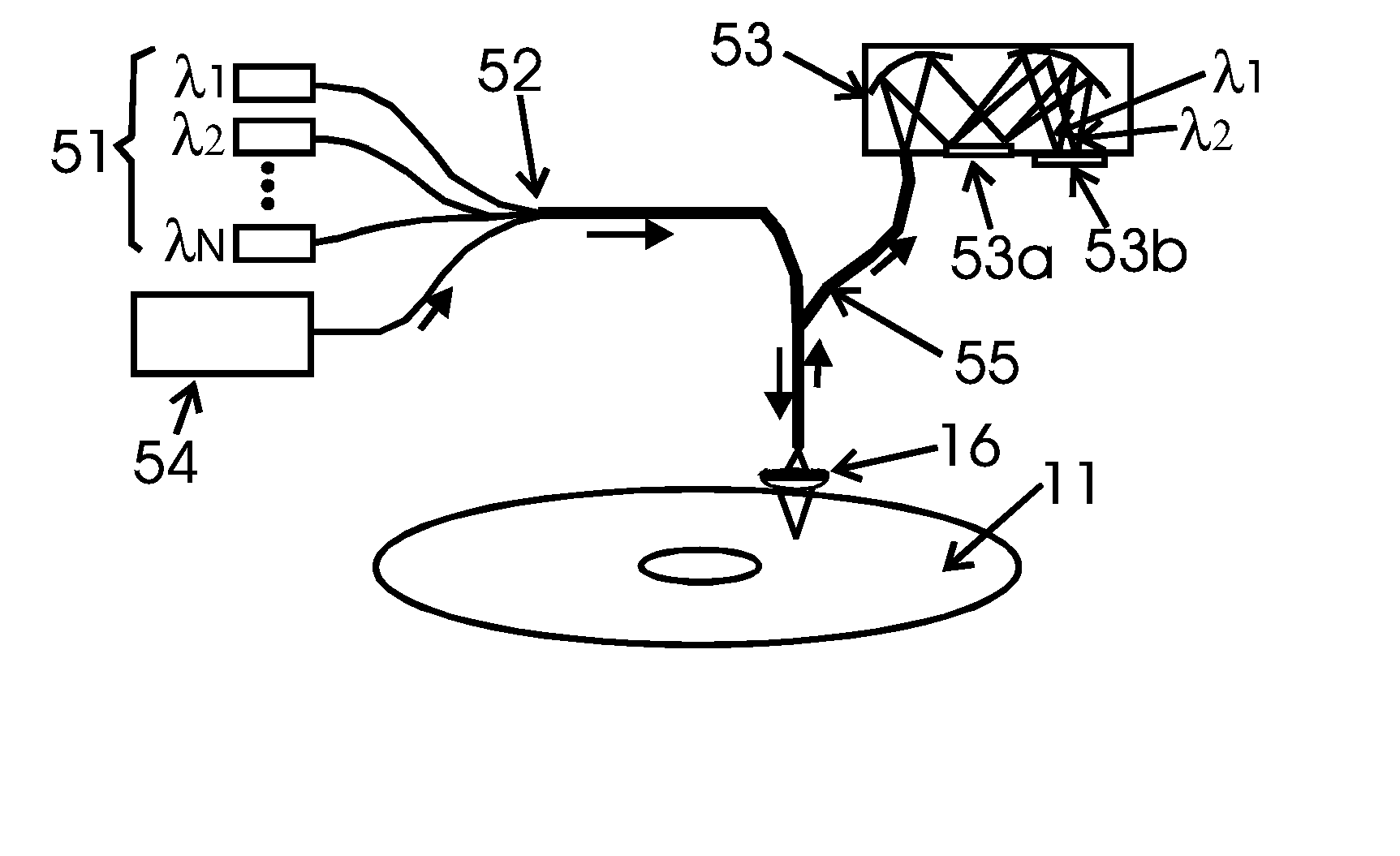
[0010] It is therefore an object of the present invention to provide an optical disk data storage system that has high storage density and fast access rate by coding multiple bits on a single pit that may be a diffraction limited pit.
[0012] It is another object of the present invention to provide an optical disk data storage system that can use various light sources including both coherent and non-coherent sources for recording and readout so as to reduce the system cost.
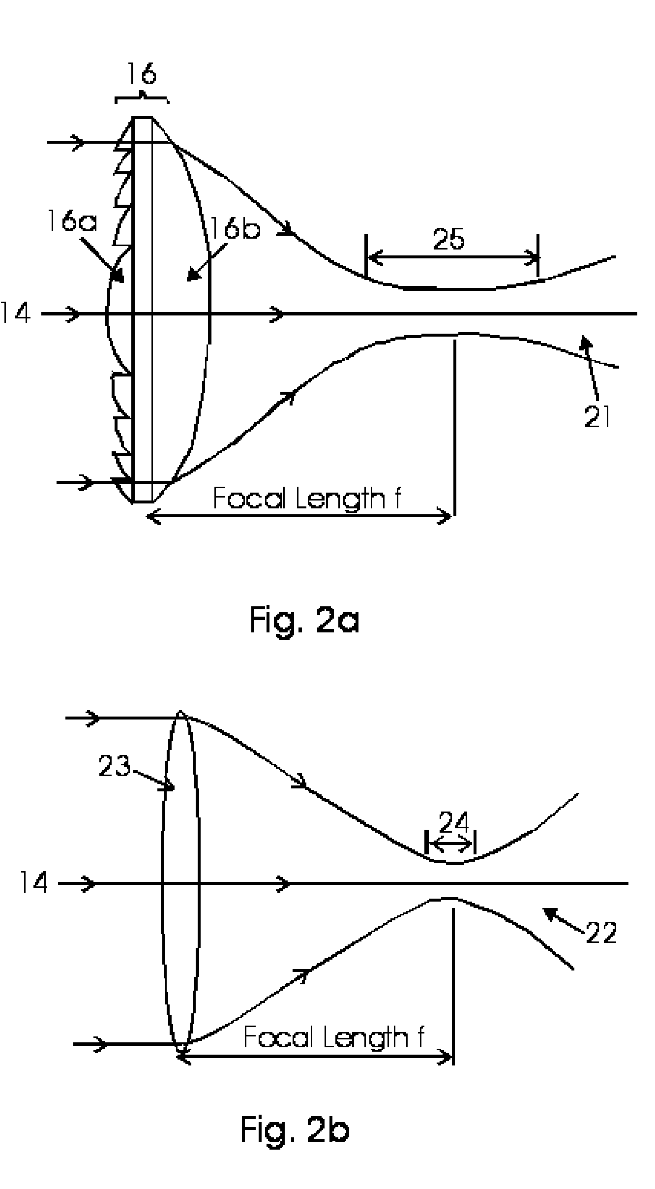
[0013] It is yet another object of the present invention to apply a specially designed objective lens system with property of extended depth of focus to create diffraction limited spot size with long focal depth of the recording beam for minimizing crosstalk between stored pits in a thick storage film. SUMMARY OF THE INVENTION

Problems solved by technology

The traditional magnetic disk storage has now reached its performance limitations.
Higher storage density becomes harder and harder to achieve on these magnetic disks and close head-to-media spacing makes high density drives no longer removable.
Despite the high storage density achieved, the holographic storage requires critical vibration-free recording and readout setups.
Many of them suffer from destructive readout problems.
Volume holographic storage is presently far from commercial uses.
The disk storage density bottleneck problem is mainly the storage coding technique.
Although there have demonstrated some proof-of-principle results, a number of issues must be addressed before these technologies can be considered for commercial applications, such as overall system reliability, bit stability, tip / medium wear, limits of data rate, signal to noise ratio, and cost.
These near field techniques even if successful would require high-resolution servo scanning that is very costly.
Furthermore, the high precision scan readout is slow limited by the trade-off between scanning speed and scanning accuracy.
Such technique cannot well use high-speed electronics to increase data access rate since the limitation comes from the readout scanning.
Such trend of reducing pit size increases recording and readout difficulty that makes newer technologies more difficult to be commercially implemented.
Although with successful demonstration of the micro holographic multiplexing method for high density data storage, there are some limitations that may obstruct this concept from practical commercial systems.
First, the hologram recording needs highly coherent light sources (laser lines).
It is difficult to find multiple laser lines with nearly equal wavelength intervals in the sensitivity range of a recording material.
The cost of using these lasers is high.
Another issue is that the recording spot size cannot remain the same diffraction limited size along the propagation path of the beam in the recording medium.
This effect limits the achievable recording density.

Method used


Image

  • Method and Device for High Density Optical Disk Data Storage
  • Method and Device for High Density Optical Disk Data Storage
  • Method and Device for High Density Optical Disk Data Storage

Examples


Embodiment Construction

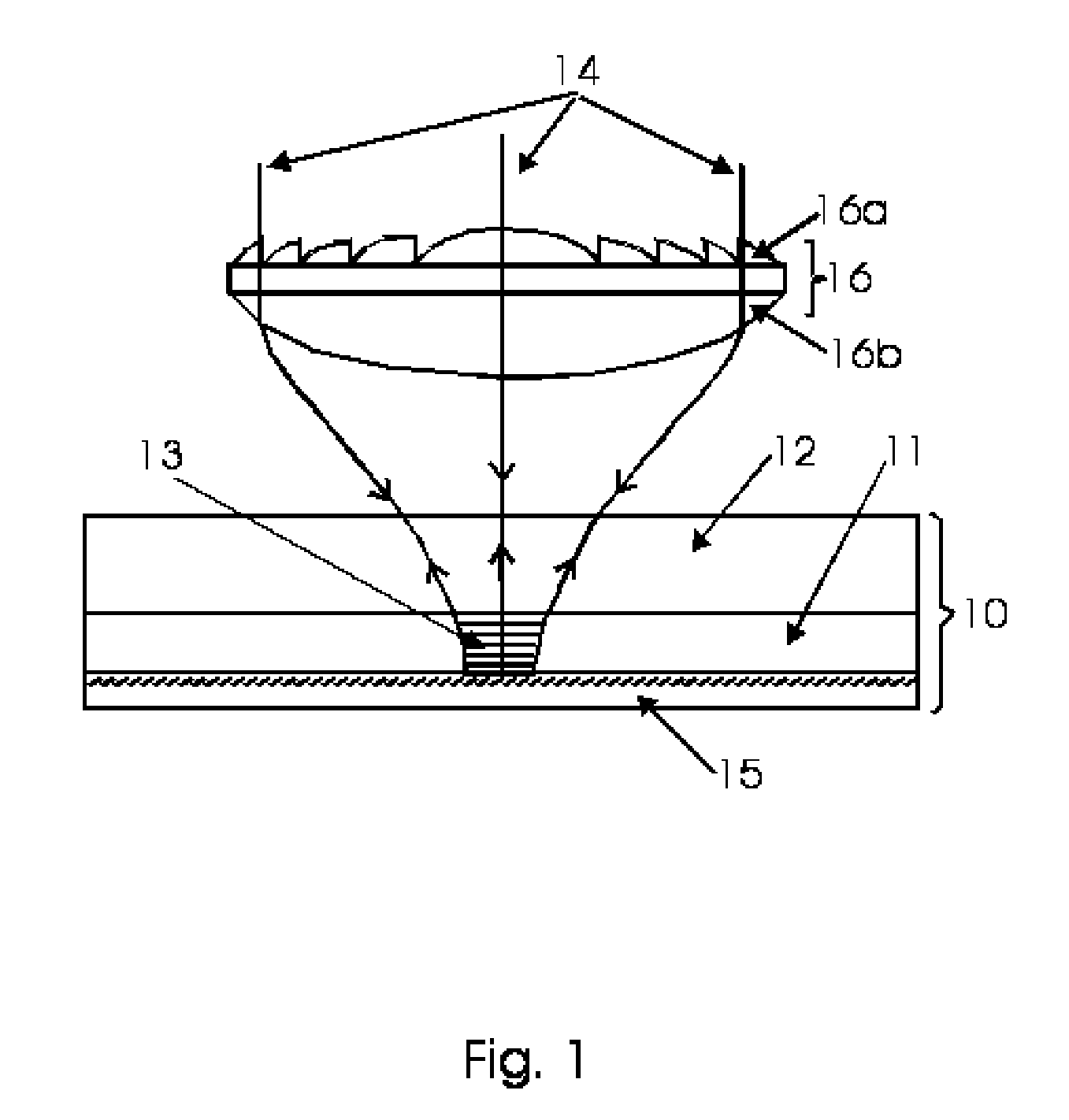
[0028]FIG. 1 is a schematic showing the recording of reflection grating in the recording medium using a pseudo non-diffracting beam with extended depth of focus property. The storage disk 10 can be created by coating a photosensitive film 11 on the substrate 12 with size of a standard CD / DVD disk. Dupont's photopolymer materials, such as HRF-700 and HRF-800, are examples of currently available candidates of recording medium. Reflection grating 13 can be recorded in the film by the illumination of a monochromatic or narrowband beam 14 along with a high reflectivity reflection mirror 15. This way, grating recording requires only one beam. It has minimal requirement on light coherent length since it minimized optical path difference between the incident beam and the reflected beam. Lower cost semiconductor laser or even narrowband spectral lines obtained from white light sources can be used. The illuminating beam first enters the recording medium 11 and then is reflected back from the ...


PUM

PropertyMeasurementUnit
diameteraaaaaaaaaa
wavelengthsaaaaaaaaaa

Abstract

This invention describes a novel coding and implementation techniques for high-speed high-density optical disk data storage. Multiple narrowband spectral beams, either coherent or non-coherent, are combined together by optical fiber couplers or lenses assembly and are then focused into a photosensitive film with diffraction limited spot size through a specially designed hybrid diffractive / refractive lens with extended depth of focus, so that the beam size remains diffraction limited size in the whole depth of the recording medium volume. Multiple reflection gratings which are respectively corresponding to these used spectral bands are recorded in the medium through interferences between the incident beams and the reflected beams from a reflection mirror which is attached at the back surface of the recording film. The reflected beam from the reflection mirror can also be replaced by a second focused beam (without using reflection mirror) with the beam splitted using an optical fiber splitter from the incident recording beam and using an identical lens with the same extended depth of focus property. By using white light to readout these gratings, using a spectrometer or multi-wavelength reader to acquire the reflected light, and using algorithms to analyze the spectrum, the recording information is recovered.

Description

FIELD OF THE INVENTION [0001] The present invention relates to high-speed high-density optical disk data storage, and in particular to a system and method for storing multiple-bits of data at a single diffraction limited pit. BACKGROUND OF THE INVENTION [0002] High-speed high-density data storage technologies are required in next generation information superhighway and military warfare because of increased demand in information access. The data storage technology is critical for fast computing and processing for targeting, time critical communication and control, and real-time sensor-to-shooter operations. The data storage is also critical for fast access to large intelligent database for other command and control operations. Furthermore, high-density data storage is highly demanded in computer and network applications. All these applications place high requirement on data storage systems namely high storage capacity, fast data access, and rugged system packaging. [0003] There are s...

Claims


Application Information

Patent Timeline
Patent Type & Authority Applications(United States)
IPC IPC(8): G11B7/135G11B7/12G11B7/13
CPCG03H1/26G03H1/2645G03H2001/0415G03H2001/266G03H2222/13G03H2223/16G11B7/0065G11B7/1206G11B7/13G11B7/1367G11B7/1374G11B7/24G11B7/24044G11B7/124
Inventor YANG, JIANWEN
Owner NEW SPAN OPTO TECH
Learn More