Etchant and method for forming bumps

a technology of etching and bumps, applied in the field of etching bumps, can solve the problems of reducing the size of the package structure of the flip-chip packaging process, corroding the tin solder, damage to the adhesive layer, etc., and achieves the effect of ensuring the etching selectivity and the metallurgy layer under the bump

a technology of etching and bumps, applied in the field of etching bumps, can solve the problems of reducing the size of the package structure of the flip-chip packaging process, corroding the tin solder, damage to the adhesive layer, etc., and achieves the effect of ensuring the etching selectivity and the metallurgy layer under the bump

US20070087546A1Active Publication Date: 2007-04-19ADVANCED SEMICON ENG INC

Image

  • Etchant and method for forming bumps
  • Etchant and method for forming bumps
  • Etchant and method for forming bumps

Examples


Embodiment Construction

[0016] Certain terms are used throughout the following description and claims to refer to particular system components. As one skilled in the art will appreciate, consumer electronic equipment manufacturers may refer to a component by different names. This document does not intend to distinguish between components that differ in name but not function. In the following discussion and in the claims, the terms “including ”and “comprising ”are used in an open-ended fashion, and thus should be interpreted to mean “including, but not limited to . . . ” The terms “couple ”and “couples” are intended to mean either an indirect or a direct electrical connection. Thus, if a first device couples to a second device, that connection may be through a direct electrical connection, or through an indirect electrical connection via other devices and connections.

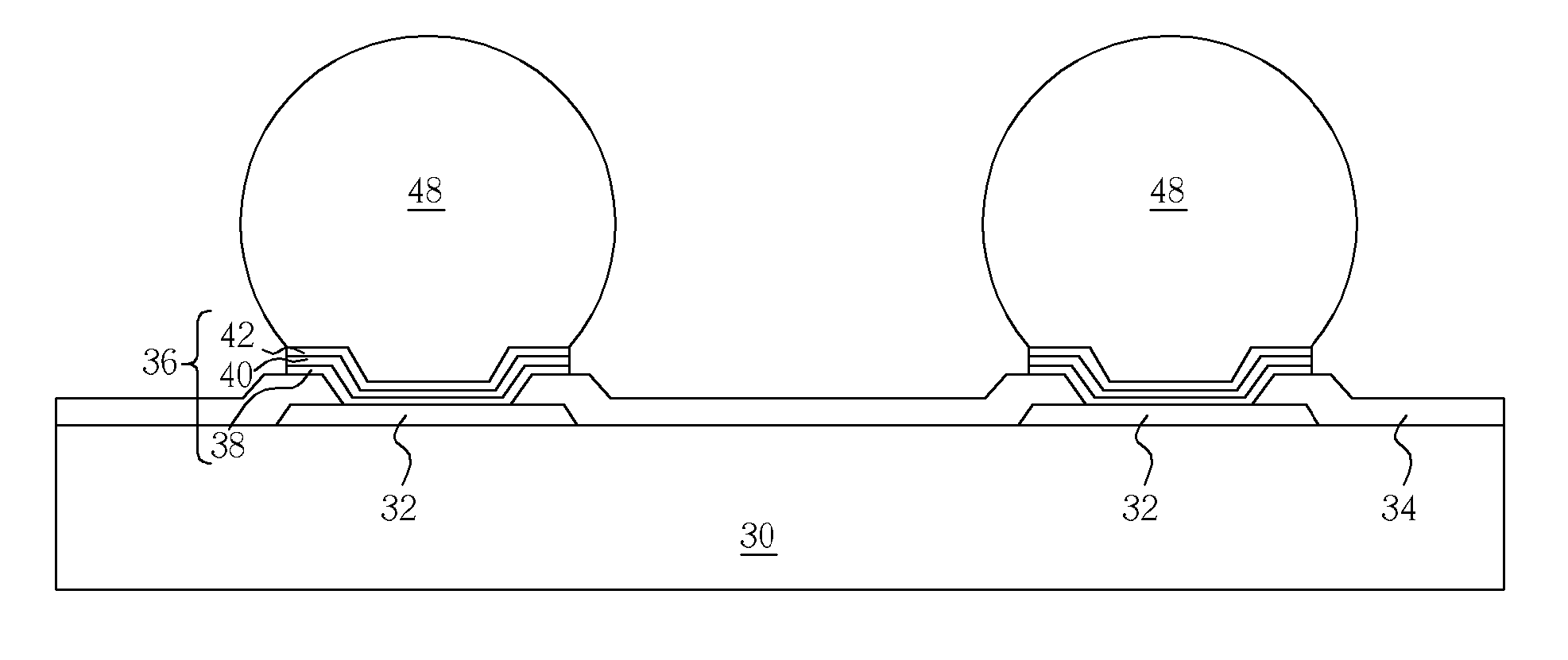
[0017] Please refer to FIG. 7 through FIG. 12. FIG. 7 through FIG. 12 are perspective diagrams showing a method of forming a bump 48 accordin...


PUM


Abstract

A method for forming bumps is disclosed. First, a substrate having an adhesive, a barrier, and a wetting layer thereon is provided. Next, a patterned photoresist is formed on the wetting layer, in which the patterned photoresist includes at least one opening for exposing a portion of the wetting layer. Next, a solder is deposited in the opening, and a stripping process is performed to remove the patterned photoresist. Next, a first etchant is utilized to perform a first etching process for etching a portion of the wetting and barrier layers by utilizing the solder as a mask, in which the first etchant is selected from the group consisting of: sulfuric acid, phosphoric acid, ferric chloride, ammonium persulfate, and potassium monopersulfate. Next, a second etchant is utilized to perform a second etching process removing a portion of the adhesive layer, and a reflow process is performed to form a bump.

Description

BACKGROUND OF THE INVENTION [0001] 1. Field of the Invention [0002] The present invention relates to a method for forming bumps. [0003] 2. Description of the Prior Art [0004] Flip-chip packaging processes are one of the most popular electronic packaging processes utilized today. In contrast to the some other packaging processes, the dies utilized in flip-chip packaging are not electrically connected to a packaging substrate via a bonding pad through a wire bonding process. Instead, the bonding pads are inverted and solder bumps are utilized to electrically connect and mount the dies onto the packaging substrate. Ideally, flip-chip packaging processes are able to achieve two important results. First, flip-chip packaging processes significantly reduce the size of package structures. Additionally, the flip-chip packaging processes are able to increase the circuit transmission between the dies and the packaging substrate. Said increase is possible because no extra wires are required for...

Claims


Application Information

Patent Timeline
19 Apr 2007
Publication
US20070087546A1
IPC
H01L21/44; H01L21/00
CPC
H01L21/32134; H01L24/11; H01L24/12; H01L2224/1147; H01L2224/13099; H01L2924/01013; H01L2924/01015; H01L2924/01022
Inventors
WU, EN-CHIEH; NG, HIEW WATT