
Multi pass gasifier

a gasifier and multi-pass technology, applied in the mechanical details of the gasifier, combustible gas production, electrochemical generators, etc., can solve the problems of difficult and expensive disposal of waste products in an environmentally acceptable manner, added to the difficulty and expense of any operation, and the end product of gasification always plagued by condensables

Inactive Publication Date: 2007-04-26
GODDARD EDWARD PASCAL
View PDF0 Cites 10 Cited by
  • Summary
  • Abstract
  • Description
  • Claims
  • Application Information

AI Technical Summary

Benefits of technology

[0004] The first object of the present invention relates to a novel approach of using the successful parameters of gasification in producing a “Tar Free” clean burning gas commonly referred to as “Producer Gas”. Another object is to have the reactor as simple as possible, and as a result has no moving parts in the reactor proper. Another object of the invention is to provide a gassifing apparatus that will accommodate a wide variety of carbons based organic fuels and also be moisture tolerant to a point. Another object is to eliminate the necessity of gas cleaning and or scrubbing. A still further object is to utilize the energy that would normally be lost with the tars. SUMMARY OF THE INVENTION
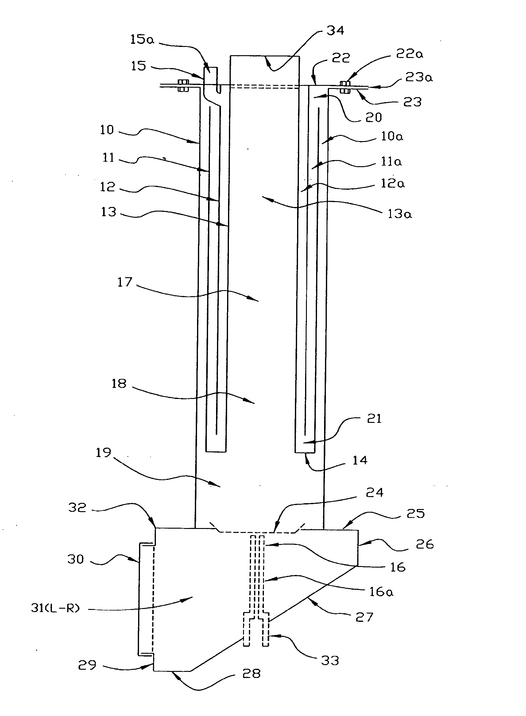
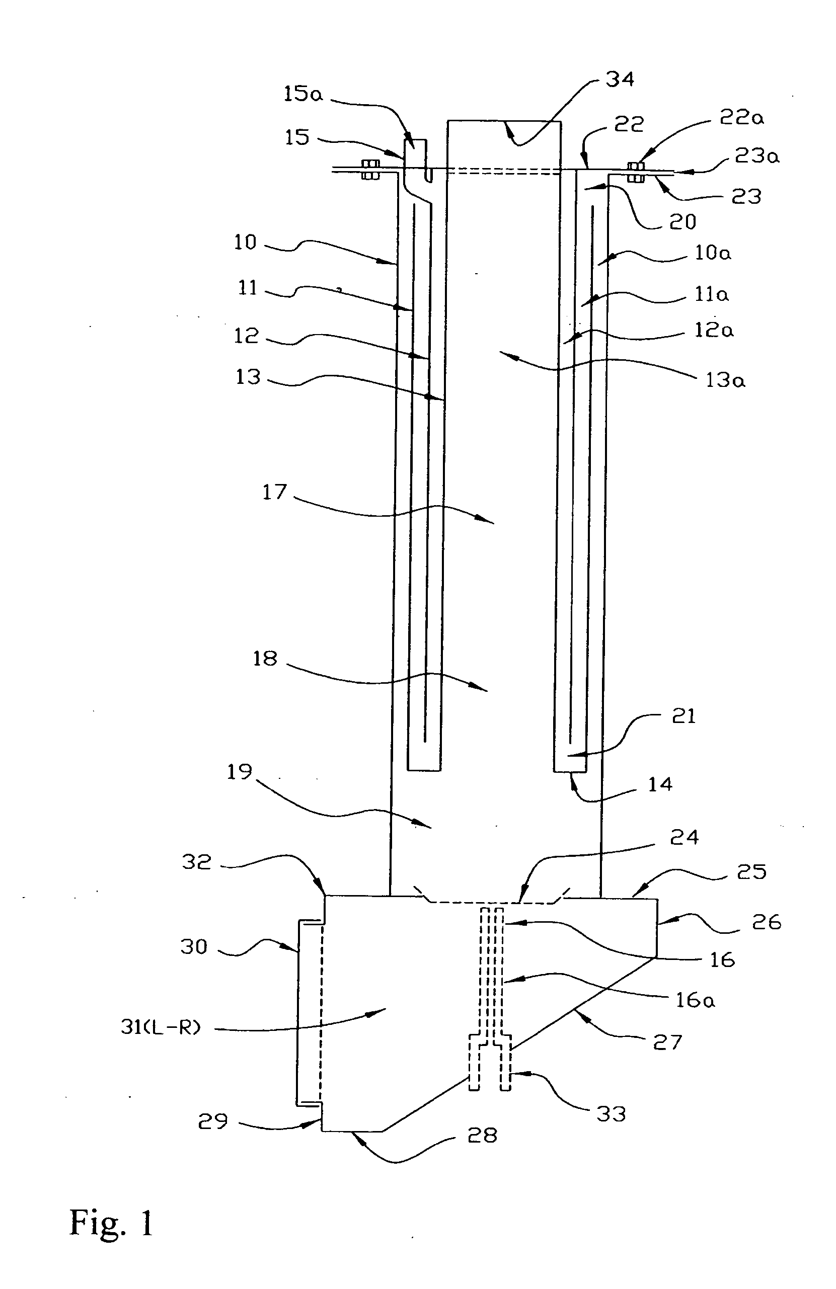
[0005] The present invention is a gasification apparatus of multi path, labyrinth configuration in which high temperature gasification is carried out by pulling a pulsating oxidizer through a nozzle just below the fire grate. This produces a high velocity stream vertically well into the several stratified zones within the reactor. The fuel feed tube and attached labyrinth encase much of the localized pyrolysis, favoring CO sub 2 and stable gaseous hydrocarbon compounds. It also favors the production of primary tars over secondary or tertiary tars. The gas stream must reverse flow around the ascending oxidizer flow to the outer portions of the feed tube causing a rotating mass of ascending-descending gases, tars and oxidizers. This combustion and gasification environment is of high temperature and time duration to enact an intense pyrolytic environment favoring stable gas production and the destruction of tars.
[0007] If used in an internal combustion engine, the engine produces the pulsating effect within the reactor. If used in another fashion, the suction blower with a well known sinusoidal wave form or air flow interrupter may be used to provide the oscillating impulses to strip boundary layer gases from combustion particles and gasifier surfaces. Said pulses of the oxidizer stream also cause a high oxidizing effect with high temperatures followed by a completely oxidizer deficient high gasification environment, resulting in an efficient production of stable gases free of entrained tars and oils.

Problems solved by technology

The end product of gasification has always been plagued with condensables in the final uses or applications.
This added to the difficulty and expense of any operation, especially in today's world of environmental and health concerns.
These waste products are difficult and expensive to dispose of in an environmentally acceptable manner.
Each classification has advantages and disadvantages yet they are all plagued by entrained condensables.
For over 150 years the gasification processes have been limited to fixed bed gasifiers and modified fixed bed gasifiers.

Method used


Image

  • Multi pass gasifier
  • Multi pass gasifier
  • Multi pass gasifier

Examples


Embodiment Construction

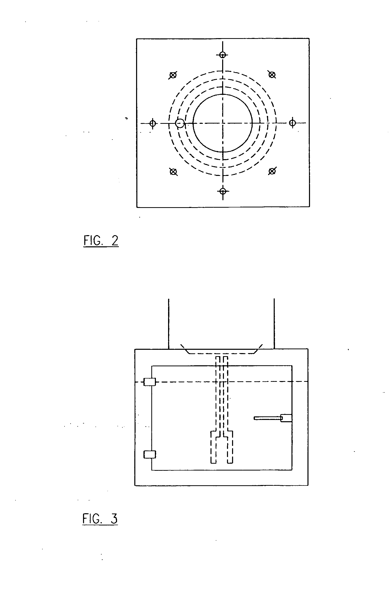
[0011] Referring now in detail to a preferred embodiment of the present invention. This is illustrated in the following figures, FIG. 1, FIG. 2, and FIG. 3. Numeral 10 in FIG. 1 denotes the outer shell or main embodiment of the reactor. The outer shell may be made from various types of metal, however due to the high temperatures and harsh environment the preferred metal should be of a high nickel alloy. Outer shell 10 is set above numeral 32, the ash collection assembly and is attached by one of the various means of metal fabrication to enact a gas tight seal. The top of the outer shell 10 has a flange, item 23, attached by one of the various means of metal fabrication to enact a gas tight seal to the top of said outer shell. Item 22 of the labyrinth assembly will provide a sealing area, by a gasket, item 23a and is bolted about its circumference to said plate, item 23. The labyrinth assembly will contain at least two gas passes, but is not limited to only two. The labyrinth assembl...


PUM

PropertyMeasurementUnit
temperatureaaaaaaaaaa
velocityaaaaaaaaaa
pressureaaaaaaaaaa

Abstract

Apparatus and method for high temperature, auto thermal gasification of solid material are disclosed. Resulting in a clean burning uniform gas usually referred to as Producer Gas. The apparatus is comprised of an outer chamber encircling a multi fold gas-path chamber that is suspended. The center of said chamber also serves as a continuous feed stock inlet. Combustion oxidizer is introduced to the lower portion of said chamber through a nozzle, just below a fire grate or screen, producing a high velocity oxidizer flow resulting in a high temperature localized heat zone. Flow is vertical through the combustion zone and into the descending feed stock, resulting in a counter-current flow. Gases and volatized tar and oil flow vertically in the space between the labyrinth and shell where said gas flow velocity is reduced considerably. Some tar and oil condensing takes place and said tar and oil flows downwardly to the heat zone to be further cracked. Said velocity reduction also inhibits particulate flow in said gas stream. Said gases enter the labyrinth as a reduced gas flow where further condensing of remaining tar and oil also takes place in the labyrinth where they will flow downwardly to the concentrated heat zone, resulting in a distilling, reducing, reacting environment. This process is repeated through the several labyrinth passes that produce the conditions and time necessary for complete cracking of the hydrocarbon compounds to a stable gas eliminating the need for tar removal equipment and or scrubbers. This utilizes more of the total B.T.U. available in the solid fuel. Evolved gases are eventually drawn off as a very uniform clean burning synthesis gas, filtered for particulates and fed directly to an internal combustion engine. Below the gasification chamber is an ash collection region, which allows for collection and removal of ash produced in the gasification process

Description

BACKGROUND OF THE INVENTION [0001] This invention relates to the conversion of hydrocarbon based organic solids. The conversion is derived by high temperature gasification into uniform clean burning gaseous fuel usually referred to as producer gas. Gasification is an old technology with many variations being applied. The process involves a complex combination of pyrolysis and oxidation reactions. Under typical gasification reactions, oxygen levels in the reactor are generally held to less than 30 percent for complete combustion. CO sub 2, CO and hydrogen are the major products. The resultant heat from this combustion causes much of the solid fuel to move through a liquid phase and then to vapor phase leaving only inert materials and ash. The end product of gasification has always been plagued with condensables in the final uses or applications. These condensables are usually referred to as tars in the general sense. Tars are generally placed into three categories: Primary, Secondary...

Claims


Application Information

Patent Timeline
Patent Type & Authority Applications(United States)
IPC IPC(8): H01M8/06
CPCC10J3/04C10J3/20C10J2200/09C10J2300/0916C10J2300/0946C10J2300/0959H01M8/0643Y02E60/50C10K3/008Y02P20/145
Inventor GODDARD, EDWARD PASCAL
Owner GODDARD EDWARD PASCAL
Learn More