Fabrication method of photomask-blank

Active Publication Date: 2007-04-26
SHIN ETSU CHEM CO LTD
View PDF2 Cites 21 Cited by
  • Summary
  • Abstract
  • Description
  • Claims
  • Application Information

AI Technical Summary

Benefits of technology

[0033] According to the first aspect of the present invention, the optical film on the transparent substrate is irradiated with flash light with the transparent substrate being mounted on the substrate supporting member made of a glass material that is opaque to the flash light. Since the transmittance of the flash light of the substrate supporting member is low, the part of the flash light that contributes to the stress control of the thin film formed on the substrate surface increases.
[0044] In addition, the reduction of the energy of the irradiation flash light has another advantage that the in-plane distribution of the optical property of the thin film can be made uniform.

Problems solved by technology

On the other hand, as can be seen from the formula (2) described above, although reduction in wavelength of the exposure light is effective for reduction in resolvable line width RP, it has a problem that it results in a reduction in depth of focus DOF, which in turn adversely affects the production yield.
However, reduction in wavelength of the exposure light results also in a reduction in depth of focus DOF and thus has a problem that it causes a focus error to reduce the production yield if the flatness of the photomask is insufficient.
However, if a stress is already accumulated in the thin film formed on the substrate at the stage of the photomask-blank, some of the stress accumulated in the film is released in the course of the pattern writing including the resist application step, the exposure step, the development step, the etching step and the resist peel-off step, thereby causing a distortion in the resulting photomask.
Such a distortion reduces the alignment precision of the photomask and causes a defect of the circuit pattern to be written.
The level of distortion depends on the pattern to be written and the magnitude of the stress accumulated in the film, and it is extremely difficult to control or release PEC-5006US the distortion during the fabrication process of the photomask.
However, it is virtually impossible to achieve this condition, because it is extremely difficult to find the fabrication process condition that satisfies both the film deposition condition that assures required properties of a thin film as an optical film and the condition for forming a thin film having a low stress.
However, a stress occurs in the film during the film deposition process, and the stress causes a distortion of the substrate and a warpage of the photomask-blank.
However, these means have a problem that the substrate itself is damaged because the temperature of the substrate is increased by excessively imparted energy or the productivity is reduced because the processing time is elongated.
However, in the case where the processing using the flash lamp is performed as described in the prior-art literature 2, the flash light irradiation causes generation of particles in the chamber by the mechanism described later, and the particles adhere to the substrate and cannot be removed by the subsequent cleaning.
Thus, there is a problem that the number of particle-caused defects of the photomask-blank increases.

Method used


Image

  • Fabrication method of photomask-blank
  • Fabrication method of photomask-blank
  • Fabrication method of photomask-blank

Examples


example 1

Reduction In Roughness of In-Chamber Surface

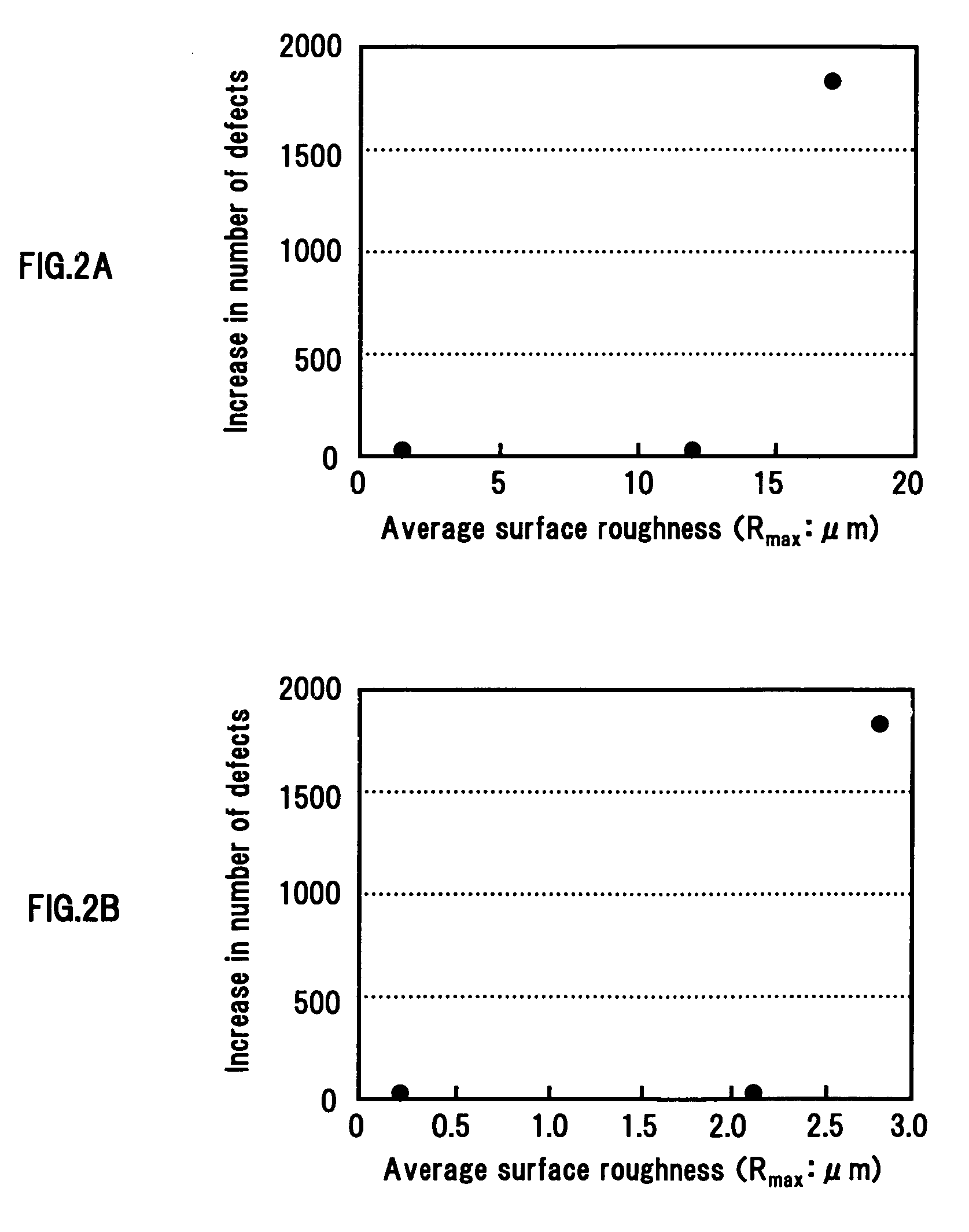
[0068] This example relates to a technique of reducing generation of particles in a flash light processing step by reducing the roughness of an in-chamber surface.

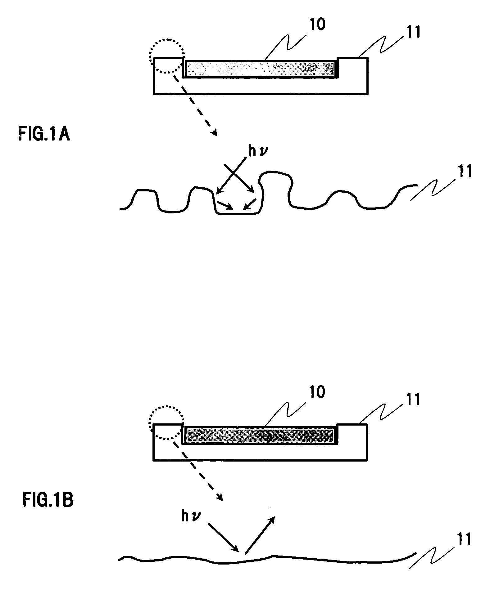
[0069] The investigation by the inventors has proven that, when the inner wall of a chamber or the surface of a jig in the chamber is irradiated with flash light, multiple reflection or the like occurs depending on the level of roughness (unevenness) of the surface, and the reflection light causes a fracture of an uneven part of the in-chamber surface, thereby producing fine particles.

[0070] In order to prevent a local fracture of the in-chamber surface due to expansion or contraction of the material thereof, quartz glass can be effectively used.

[0071] Thus, in the following description, it is supposed that the chamber and jigs, such as a susceptor, housed in the chamber are made of quartz glass, unless otherwise specified. As described in detail later, the quartz glass has a...

example 2

Investigation of Pressure In Chamber

[0094] This example relates to the influence of the pressure in a chamber during flash light irradiation on the generation of particles.

[0095] The investigation by the inventors has proven that generation of particles can be effectively suppressed by reducing the pressure in the chamber in which flash light irradiation occurs.

[0096] According to prior art, when performing flash light irradiation, the chamber is once evacuated, nitrogen gas is introduced into the chamber through a filter capable of removing particles having a diameter of 0.1 μm, for example, and then flash light irradiation is performed at atmospheric pressure while flowing the clean nitrogen gas. However, it has been proven by experiment that, if the flash light irradiation is performed at atmospheric pressure in this way, a large amount of defects occur with a certain probability (frequency). The inventors have considered this phenomenon as described below.

[0097]FIGS. 3A and ...

example 3

Structure 1 of Susceptor

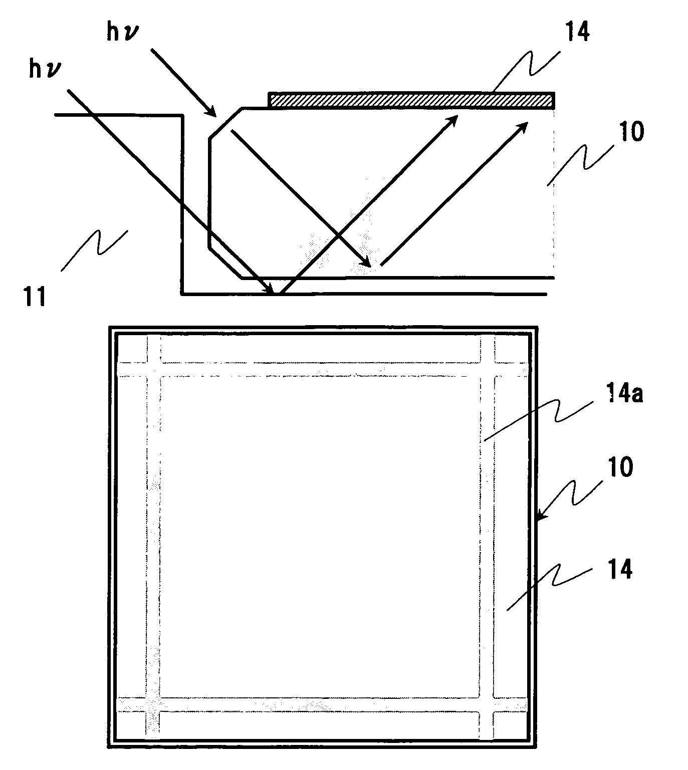
[0110] This example relates to a structure of a susceptor on which a substrate is mounted during flash light irradiation, which is intended to reduce particles generated during flash light irradiation by minimizing the amount of irradiation light of a flash lamp.

[0111]FIGS. 6A and 6B are diagrams for illustrating behaviors of light from a flash lamp after being perpendicularly incident on a substrate mounted on a susceptor and passing through the substrate with regard to susceptors of different structures. The susceptor shown in FIG. 6A is made only of transparent quartz, and the susceptor shown in FIG. 6B s made only of opaque quartz.

[0112] The term “susceptor” in this specification is used in a broad sense to refer to a member for holding a substrate for a member on which a substrate is mounted). Therefore, the shape or the like of the susceptor is not limited to that illustrated in these drawings. In addition, quartz glass, which is described as the mat...


PUM

PropertyMeasurementUnit
Fractionaaaaaaaaaa
Fractionaaaaaaaaaa
Wavelengthaaaaaaaaaa

Abstract

A susceptor having the most basic structure has a three-layer structure including a first and a second transparent quartz part and an opaque quartz part sandwiched therebetween. For example, the opaque quartz part is made of“foamed quartz”. In addition, the opacity of the opaque quartz part to flash light is determined to fall within an appropriate range based on the material or thickness of the opaque quartz part, taking into consideration the composition or thickness of a thin film formed on the substrate and various conditions concerning the energy of the irradiation light during flash light irradiation or the like. The stack structure may be composed of a stack of a plurality of opaque quartz layers having different opacities.

Description

BACKGROUND OF THE INVENTION [0001] 1. Field of the Invention [0002] The present invention relates to a fabrication method of a photomask-blank. In particular, it relates to a fabrication technique of a photomask-blank, which is a base material for a photomask, which is used for fine processing of a semiconductor integrated circuit, a charge-coupled device (CCD), a color filter for a liquid crystal device (LCD), a magnetic head and the like. [0003] 2. Description of the Related Art [0004] The packaging density of semiconductor integrated circuits is becoming higher, and the wavelength of exposure light of exposure apparatus used in the lithography technique for fabrication of semiconductor integrated circuits or the like is becoming shorter in order to improve the resolution. According to the lithography roadmap of International Technology Roadmap for Semiconductor (ITRS) updated in 2004, the dominant light sources are shifting from ultraviolet light sources of g-line (wavelength λ=4...

Claims


Application Information

Patent Timeline
IPC IPC(8): B32B9/00B32B17/10G03F1/00B32B17/06
CPCG03F1/14G03F1/32Y10T428/31616G03F1/50G03F1/62
Inventor FUKUSHIMA, NORIYASUYOSHIKAWA, HIROKIKANEKO, HIDEOINAZUKI, YUKIO
Owner SHIN ETSU CHEM CO LTD
Why Eureka
Try Eureka