LED apparatus with temperature control function

Inactive Publication Date: 2007-06-21
POLYTRONICS TECH
View PDF3 Cites 28 Cited by
  • Summary
  • Abstract
  • Description
  • Claims
  • Application Information

AI Technical Summary

Benefits of technology

[0008] The objective of the present invention is to provide an LED apparatus having temperature control functions such as over-temperature protection or temperature adjustment. The current flowing through the LED can be significantly decreased whenever the temperature of the LED is too high or exceeds a threshold value, thereby rapidly decreasing the heat generation so as to prevent the LED from being damaged. Alternatively, the current flowing through the LED can be promptly decreased when temperature of the LED start to increase, so that the temperature of the LED can not exceed the threshold value.
[0010] According to one aspect of the present invention, the PTC device serves for over-current circuit protection. In an electric circuit, many incidents, such as hot plug, on-off switch, power surge, etc., could bring in-rush current to the system. Under the over-current condition, the PTC device switches to high resistance state. Thus, the in-rush current could be eliminated and the protection of the LED circuit could be achieved.
[0011] According to another aspect of the present invention, the PTC device could also be used for LED over-temperature protection based on its inherent temperature sensing characteristics and its abrupt increase of resistance when temperature exceeds its switching temperature. The switching temperature is defined as the temperature at which PTC resistance raises to 10 times of its initial room temperature resistance. Once PTC senses the heat build-up around LED to a dangerous level, the PTC switches to a high resistance state and rapidly drops the input current to a very low level. This current limiting behavior of PTC is especially useful for preventing LED from thermal-run-away.
[0018] The heat conductive layer is made by blending polymer and at least one high heat conductive dielectric filler with greater than 40% volume ratio and followed by pressing. Because polymer is easy to be treated and processed in comparison with other metallic or ceramic materials and is dielectric, it is suitable for use as the matrix of the heat conductive layer. Almost all polymers can be used for this application and not limited to the following materials: rubber (e.g., natural rubber, silicone, isobutylene rubber, SBS, or liquid rubber CTBN), thermoset resins (e.g., epoxy, polyurethane or polyester) or thermoplastic resins (e.g., polyethylene, polyvinyodene fluoride, polypropylene, Nylon, polyester, ABS or copolymer thereof). In order to increase mechanical strength and stability at high temperature of the thermoplastic resins, the thermoplastic resins can be further subjected to a cross-linking process such as radiation or addition of a chemical cross-linking agent. The thermoset resins can comprise functional groups such as amine, acid, anhydride, isocyanate, halogen, alcohol and epoxide.
[0021] The temperature control device comprises two electrode foils and a temperature sensitive layer laminated therebetween. The polymeric temperature sensitive layer exhibits PTC behavior and comprises crystalline polymer or blend of crystalline polymers, and electrical conductive filler. The switching temperature, which is governed by the melting temperature of crystalline polymer, ranges from 45° C. to 300° C., preferably from 60° C. to 250° C., most preferably from 80° C. to 180° C. The two electrode foils are used to electrically connect to the LED chip and the second electrode. Moreover, one of the electrode foils can be separated into two foil members, which are positioned at the same side of the temperature sensitive layer, for electrical connection. Accordingly, the electrode foils at the same side or at different sides can be selected for electrical connection, thus the manufacture is more flexible.

Problems solved by technology

In an electric circuit, many incidents, such as hot plug, on-off switch, power surge, etc., could bring in-rush current to the system.

Method used


Image

  • LED apparatus with temperature control function
  • LED apparatus with temperature control function
  • LED apparatus with temperature control function

Examples


Embodiment Construction

[0027] The present invention will be explained with the appended drawings to clearly disclose the technical characteristics of the present invention.

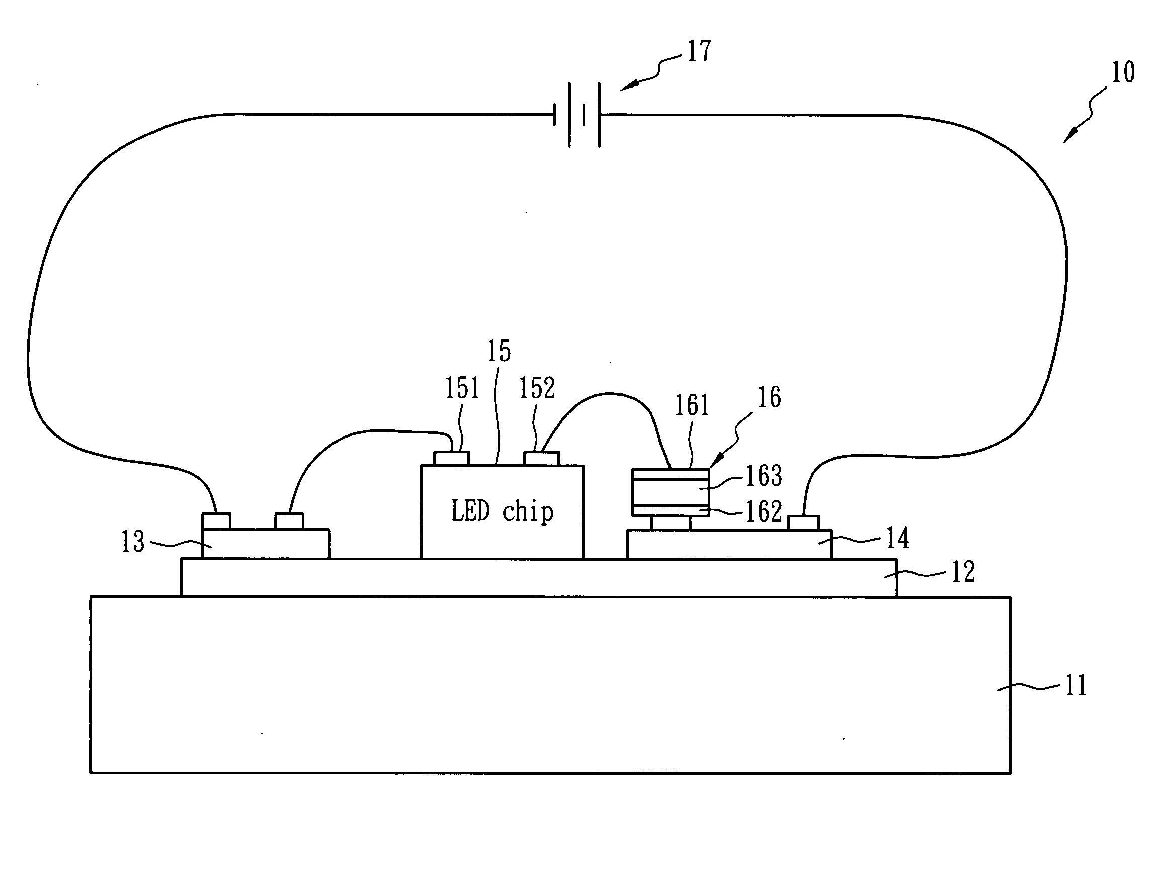
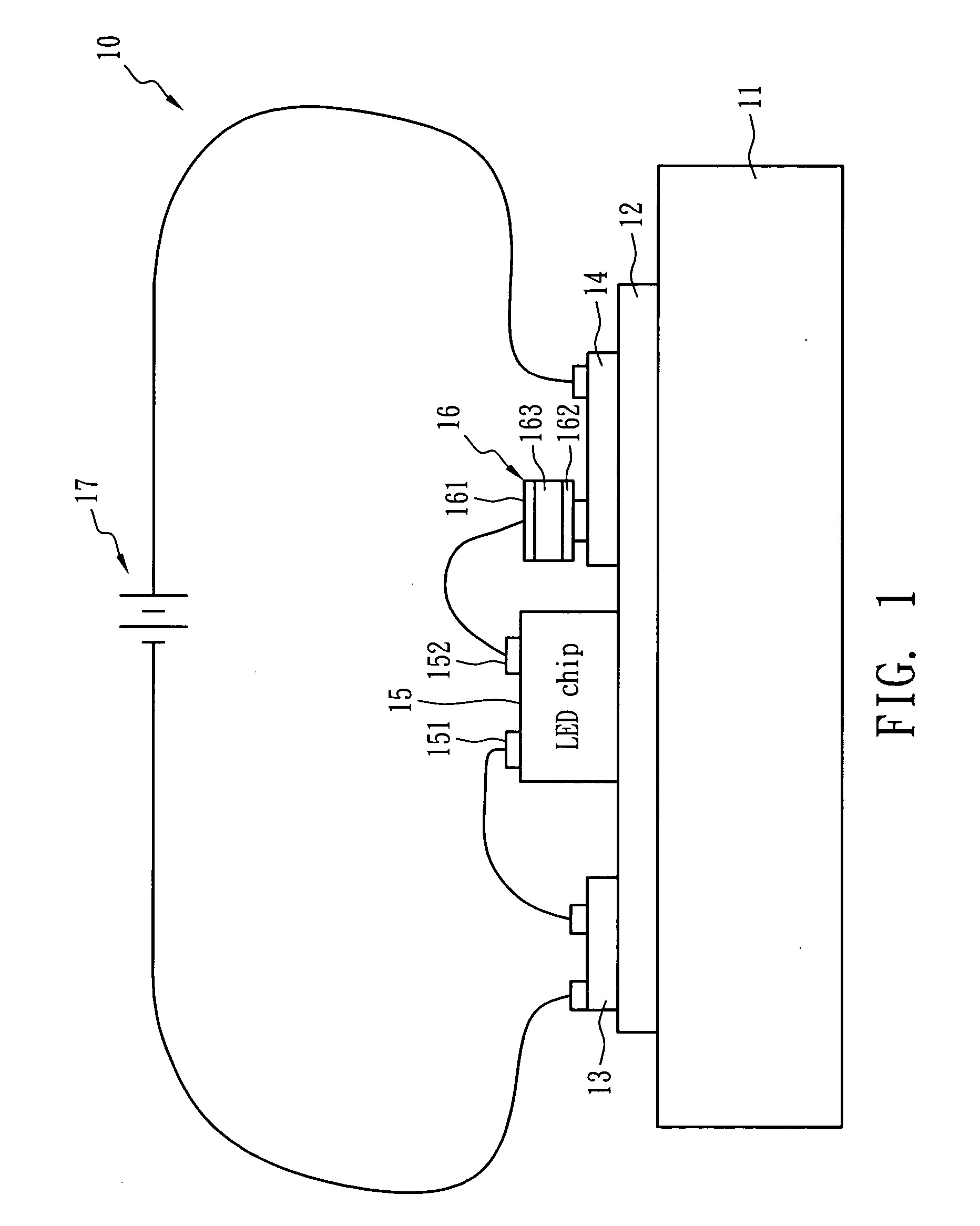
[0028]FIG. 1 illustrates an LED apparatus with temperature control function in accordance with an embodiment of the present invention. An LED apparatus 10 comprises a heat dissipation plate 11, a heat conductive layer 12, a first electrode 13, a second electrode 14, an LED chip 15 and a temperature control device 16. The LED chip 15, the first electrode 13 and the second electrode 14 are disposed on a side of the heat conductive layer 12, and the other side of the heat conductive layer 12 is in contact with the heat dissipation plate 11 so as to dissipate the heat of the LED chip 15. In short, the heat conductive layer 12 and heat dissipation plate 11 are used for carrying the LED chip 15 and for heat dissipation while the LED chip 15 illuminates.

[0029] The distance between the temperature control device 16 and the LED chip 15 is less...


PUM


Abstract

An LED apparatus with temperature self-regulating, over-temperature protection, and over-current protection function comprises an LED chip, a heat dissipation plate, a heat conductive layer and a temperature control device. The heat dissipation and the heat conductive layer disposed thereon carry the LED chip and dissipate the heat generated from the LED chip that is connected to an electric power source for luminance. The temperature control device exhibiting PTC behavior is electrically connected between the LED chip and the electric power source in series, and the distance between the LED chip and the temperature control device is less than 3 cm. The heat conductive layer can consist of polymeric dielectric material and has a heat conduction coefficient larger than 1.0 W / mK at 25° C.

Description

BACKGROUND OF THE INVENTION [0001] (A) Field of the Invention [0002] The present invention is related to an LED (light emitting diode) apparatus, more specifically, to an LED apparatus having temperature control functions. [0003] (B) Description of the Related Art [0004] In recent years, white light LED is an attractive new product with increasing importance around the world. It has the advantages of small volume, low power consumption, long lifetime and quick response, and can solve many problems that exist with an incandescent lamp. [0005] In view of the consensus of Japan, European countries, and the U.S. on power saving and environmental protection, the countries are actively developing white light LED as the luminance source for this century. In addition, if all incandescent lamps are replaced with white light LEDs, electric power consumption can be diminished and carbon dioxide (CO2) generation can be decreased so as to reduce the greenhouse effect. Accordingly, European count...

Claims


Application Information

Patent Timeline
IPC IPC(8): F21V23/04
CPCH01L25/167H05B33/0821H05B33/0854H05B33/089Y02B20/341H01L2224/48137H01L2224/48091H01L2924/00014H01L2224/73265H05B45/40Y02B20/30H05B45/18H05B45/56
Inventor WANG, SHAU CHEWYU, JYH MING
Owner POLYTRONICS TECH
Why Eureka
Try Eureka