Porous medical device and method for its manufacture

Active Publication Date: 2007-06-21
BIORETEC
View PDF20 Cites 89 Cited by
  • Summary
  • Abstract
  • Description
  • Claims
  • Application Information

AI Technical Summary

Benefits of technology

[0012] The thickness of the device can be varied by selecting the number of textile layers to be piled. The porosity can be controlled by choosing the size of the openings (mesh size) in the layers. The porosity in the direction of thickness of the device can also be varied by varying the size or form of the openings or the textile type in the same structure. If the device of constant thickness is not desired on the final implantation site, the device can be made into the 3-dimensional shape fitting to the body by piling layers of selected shape one on top of the other and stiffening t

Problems solved by technology

However, this procedure implies the loss of function and disability that, although, temporary, it can lead to complications.
For a body frame-keeping, load bearing system comparable to bone, it has been difficult to develop reliable biomaterials that are biocompatible, temporarily present in the body (elimination by body itself), and mechanically reliable.
These polymers as such may not always possess sufficient strength to bear weight and an additional supporting mechanism is needed to help bone in weight-bearing which the function of the scaffold is limited to support the healing of

Method used


Image

  • Porous medical device and method for its manufacture
  • Porous medical device and method for its manufacture
  • Porous medical device and method for its manufacture

Examples


example of an embodiment (

NON-LIMITING)

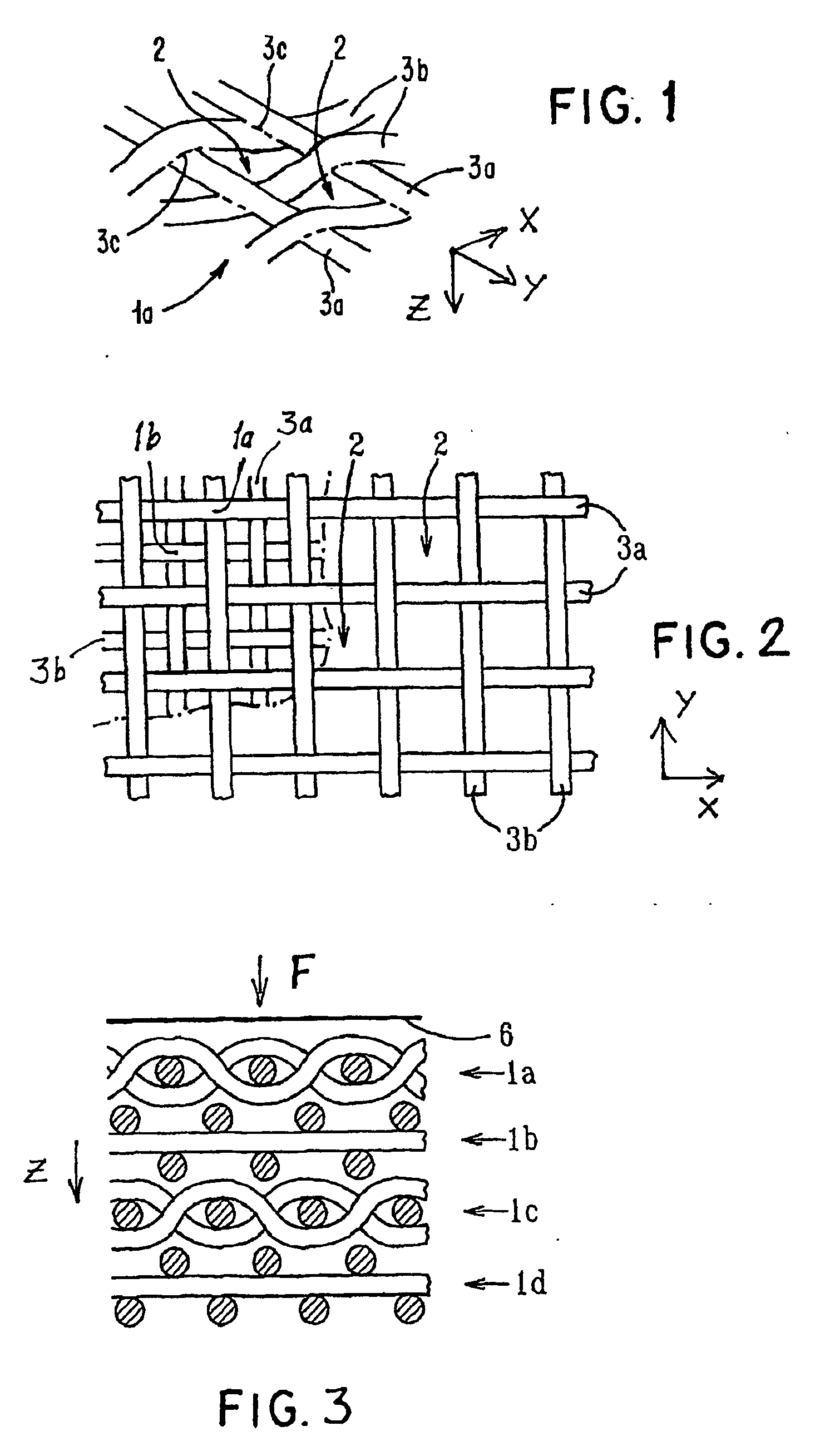
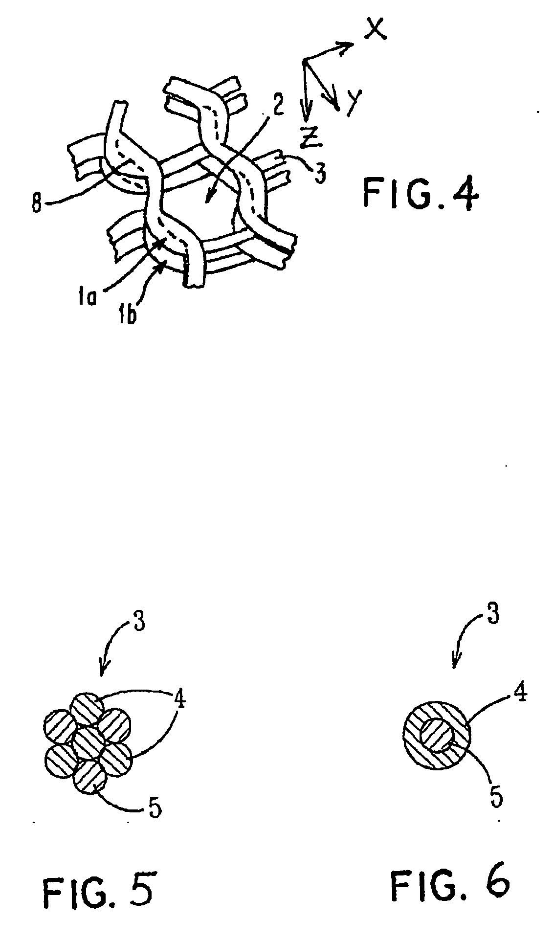
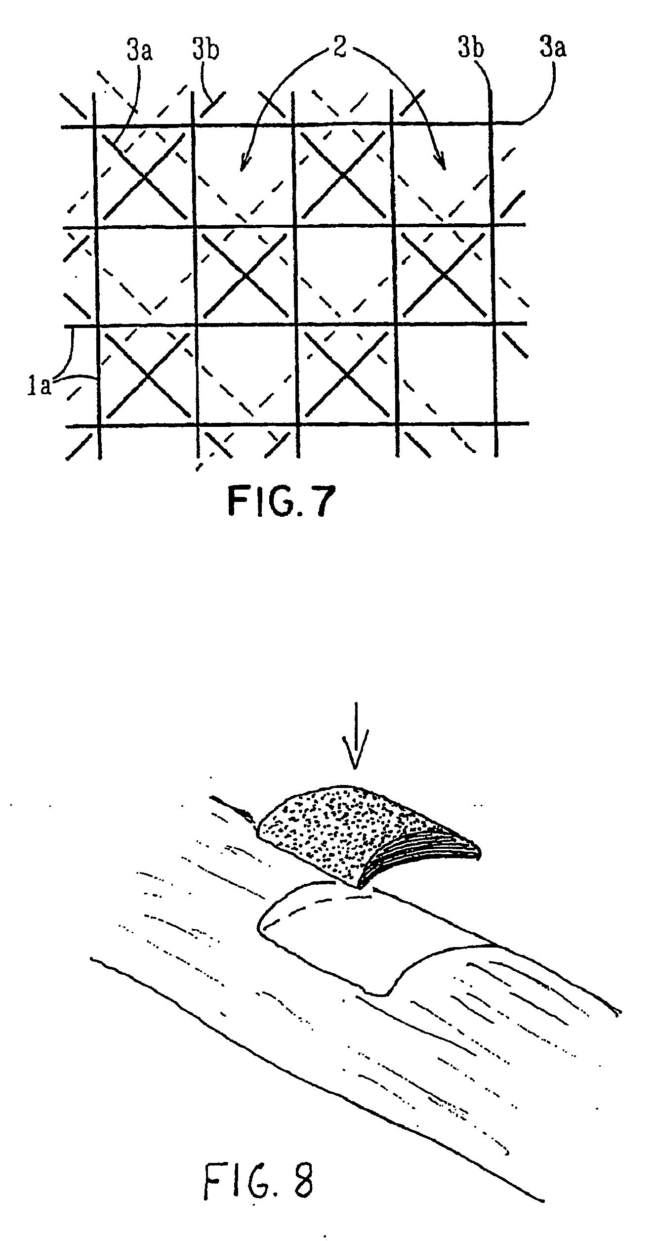
[0103] Starting materials were continuous monofilament of bioabsorbable PLLA made by fiber spinning with a diameter about 200-300 μm and bioactive glass made by spinning with a diameter 20-30 μm. These filaments were knitted together by a flat-bed knitting machine Stoll UFD with an interlock setting. Pieces of 300×300 mm were cut from the knit and four of them were piled on top of each other so that the orientations of the different layers in the machine direction coincided. The melting point of the matrix polymer used being 180° C., the laminate blank was compression moulded into a porous cellular plate at a temperature of 110-130° C., which was the range set for the machine. At the processing stage, a set of temperature and pressure (100-150 kN) profiles as a function of time was followed. Finally, the piece was air cooled under a weight of 30 kg. The thickness of the laminate was about 6 mm and the density with pores was 500 kg / m3, Samples of the cellular plate were ...


PUM

PropertyMeasurementUnit
Pressureaaaaaaaaaa
Structureaaaaaaaaaa
Dimensionaaaaaaaaaa

Abstract

Porous bioabsorbable, bioactive and load-bearing composite medical device structure includes a plurality of regular textile planar layers (1a, 1b . . . ) formed of continuous bioabsorbable polymer matrix and bioceramic fibers acting as reinforcements, both included in continuous fibrous elements (3) forming the textile layers. The layers are placed on top of each other to form a structure having two dimensions (x, y) at right angles to each other according to the two dimensions of the textile layer and a third dimension (z) perpendicular to them and resulting from the piling of the layers. A plurality of passages extend through the layers as a result of the openings (2) defined by portions of the continuous fibrous elements (3) extending substantially in the direction of the plane. The continuous fibrous elements (3) comprise both bioactive ceramic reinforcing fibers which form a reinforcing structure and a bioabsorbable polymer matrix material which forms a matrix which binds the layers together and also binds the portions of continuous fibers defining the openings together, thereby forming the passages and stiffening the structure. This bioactive and bioabsorbable composite structure is suitable to be used as a basic structure in medical devices, especially in osteochondral applications where the load-bearing properties of implant are required.

Description

FIELD OF THE INVENTION [0001] The invention relates to a porous bioabsorbable, bioactive and load-bearing composite medical device structure and to a method for manufacturing a structure of this kind. BACKGROUND OF THE INVENTION [0002] So far, various medical composite materials have been developed to address the problem of wound healing. Man has long searched for proper materials to aid healing and regeneration of tissues or their replacement when the first option fails. Man has borrowed solutions and materials from nature. The first biomaterials used by man were derived from naturally occurring materials such as catgut that has been documented used by old Egyptians. Indians have used various replacement materials. For demanding tissues where mechanical properties are important, i.e. hard tissues for their primary function to keep the frame of the body, cartilage and bone were thus treated mainly with splinting and immobilization. However, this procedure implies the loss of functio...

Claims


Application Information

Patent Timeline
IPC IPC(8): A61K48/00B32B27/04A61F2/00A61F2/02A61F2/28A61F2/30A61L27/44A61L27/56A61L27/58B32B5/26D04B1/14
CPCA61F2/28A61F2/3094A61F2/30965A61F2002/2817A61F2002/30062A61F2002/30065A61F2002/30677A61F2002/30678A61F2002/30914A61F2002/30915A61F2002/30971A61F2210/0004A61F2210/0071A61F2310/00179A61F2310/00293A61L27/44A61L27/56A61L27/58B32B5/26D04B1/14D10B2509/08D02G3/448D04C1/06Y10T442/2525B32B2255/26B32B2305/08B32B2255/02B32B2556/00B32B2262/105
Inventor SUOKAS, ESATORMALA, PERTTIASHAMMAKHI, NUREDDINYLANEN, HEIMOHUPA, MIKKO
Owner BIORETEC
Why Eureka
Try Eureka