Corrosion resistant material for reduced fouling, a heat transfer component having reduced fouling and a method for reducing fouling in a refinery

a technology of corrosion resistance material and heat transfer component, which is applied in the direction of corrosion prevention, thin material processing, coatings, etc., can solve the problems of corroding and the build-up of deposits, and affecting the optimal control of the heat exchanger, so as to reduce corrosion and fouling, reduce the effect of fouling and easy determination of the upper temperature constraints

Inactive Publication Date: 2007-07-12
EXXON RES & ENG CO
View PDF27 Cites 23 Cited by
  • Summary
  • Abstract
  • Description
  • Claims
  • Application Information

AI Technical Summary

Benefits of technology

[0017] The formation of the Cr-enriched layer is not limited to the use of electro-polishing; rather, numerous other formation techniques are considered to be well within the scope of the present invention including but not limited to electroplating, bright annealing, passivation, thermal spray coating, laser deposition, sputtering, physical vapor deposition, chemical vapor deposition, plasma powder welding overlay, cladding, and diffusion bonding. It is contemplated that the corrosion resistant material, disclosed herein, may be used in other applications to reduce corrosion and fouling.
[0018] Each of the surfaces in the heat transfer components and particularly the heat exchanger tubes in accordance with the present invention preferably has a protective layer formed thereon. The surfaces of the baffles and the tube sheets may also include an enriched layer. The protective layer is preferably formed on the outer surface of the Cr-enriched layer. The protective layer may be an oxide layer, a sulfide layer, an oxysulfide layer or any combination thereof. The protective layer preferably includes a material selected from the group consisting of a magnetite, an iron-chromium spinel, a chromium oxide, oxides of the same and mixtures thereof. In the accordance with the present invention, the protective layer is preferably formed on the Cr-enriched layer after the heat exchanger tubes are located within the exchanger and the heat exchanger is operational. The protective layer forms when the Cr-enriched layer is exposed to the process streams (e.g., petroleum stream or vacuum residual stream or air) and high temperatures. The temperature at which the protective layer forms varies. In a late-train heat exchanger applications, the protective layer forms at temperatures up to 400° C. In applications in a furnace or outside the late-train heat exchanger, the protective layer forms at temperatures up to 600° C. In petrochemical applications including use in steam cracker and reformer tubes, the protective layer forms at temperatures up to 1100° C. The temperatures utilized during the formation of the protective layer will be dependent on the metallurgy of the steel being acted upon. The skilled artisan can easily determine the upper temperature constraints based on the steel's metallurgy.
[0019] It has also been found that aluminum or aluminum alloy coated carbon steels are effective in reducing fouling. The surfaces of these coated steels have a surface roughness of less than 40 micro inches (1.1 μm), preferably less than 20 micro inches (0.5 μm) and more preferably less than 10 micro inches (0.25 μm). Similarly, titanium and titanium alloys can be effective in reducing fouling. The desired surface roughness may be obtained by electropolishing or honing the aluminum or titanium coating. The desired surface roughness may also be obtained by abrasive finishing methods including but not limited to precision grinding, microgrinding, mechanical polishing, lappling and heat treatment during the coated strip forming process.
[0020] It is another aspect of the present invention to provide a method of reducing fouling in a refinery or petrochemical facility. The method may result in significant cost savings because the number of scheduled downtimes to address heat transfer component fouling is significantly reduced. Furthermore, the heat transfer components operate more efficiently because the harmful effects of fouling are reduced. The present method is especially well suited for existing heat exchangers, which may presently be plagued with fouling. The method of reducing fouling in accordance with the present invention includes removing the existing heat exchanger tubes from the heat exchanger. The method further includes installing a plurality of replacement heat exchanger tubes.

Problems solved by technology

During normal use with contact between the oil and the heat exchanger, corrosion and the build-up of deposits occurs.
This build-up of deposits is often called fouling.
Fouling adversely impacts the optimal control of the heat exchanger.
Fouling in this context is the unwanted deposition of solids on the surfaces of the tubes of the heat exchanger, which leads to a loss in efficiency of the heat exchanger.
The loss in heat transfer efficiency results in higher fuel consumption at the furnace and reduced throughput.
The buildup of foulants in fluid transfer components results in reduced throughput, higher loads on pumping devices and plugging of downstream equipment as large pieces of foulant periodically dislodge and flow downstream.
This decreases overall facility reliability due to shutdowns for maintenance.
This also leads to increased manpower requirements due to the number of cleaning crews required to service fouled heat exchanger and process fluid transfer tubes.
Another detriment is an increase in volatile organic emission resulting from the cleaning process.
During normal use, the surfaces of the tubes of the heat exchanger are subject to corrosion as a result of the prolonged exposure to the stream of crude and other petroleum fractions.
Corrosion on the surfaces of the tubes creates an uneven surface that can enhance fouling because the various particles found in the petroleum stream may attach themselves to the roughened surface.
These streams often contain solids and are high fouling.
While the problems of fouling extend beyond petroleum refining and petrochemical processing, the presence of crude oil presents numerous obstacles in preventing fouling that are unique to petroleum refining and petrochemical processing not present in other industries.
Crude oil is a complex mixture of organic and inorganic components which may result in a variety of foulant deposits on the surfaces of the heat exchanger including but not limited to both surfaces of the heat exchanger tubes, the baffles and the tube sheets.
This material, under the right conditions, will deposit within heat exchangers resulting in depositional fouling.
These dissolved salts can also contribute to depositional fouling.
As more and more chemicals are used to enhance production of crude from old reservoirs, additional inorganic materials are coming to the refineries in the crude oil and potentially contributing to fouling.
Crude oils are typically blended at the refinery, and the mixing of certain types of crudes can lead to another type of foulant material.
Crude oils often also contain acidic components that directly corrode the heat exchanger materials as well.
Naphthenic acids will remove metal from the surface and sulfidic components will cause sulfidic corrosion which forms iron sulfide.
These synthetic crudes present additional fouling problems, as these materials are too heavy and contaminant laden for the typical refinery to process.
This, however, reduces the pool of feedstock that is potentially available to the refinery.
Again, this can reduce the feedstock potentially available to the refinery.
While these techniques are useful in reducing the rate of fouling within the heat transfer components, fouling can still occur under certain circumstances.
These devices, however, have low reliability and high maintenance needs.

Method used


Image

  • Corrosion resistant material for reduced fouling, a heat transfer component having reduced fouling and a method for reducing fouling in a refinery
  • Corrosion resistant material for reduced fouling, a heat transfer component having reduced fouling and a method for reducing fouling in a refinery
  • Corrosion resistant material for reduced fouling, a heat transfer component having reduced fouling and a method for reducing fouling in a refinery

Examples


Embodiment Construction

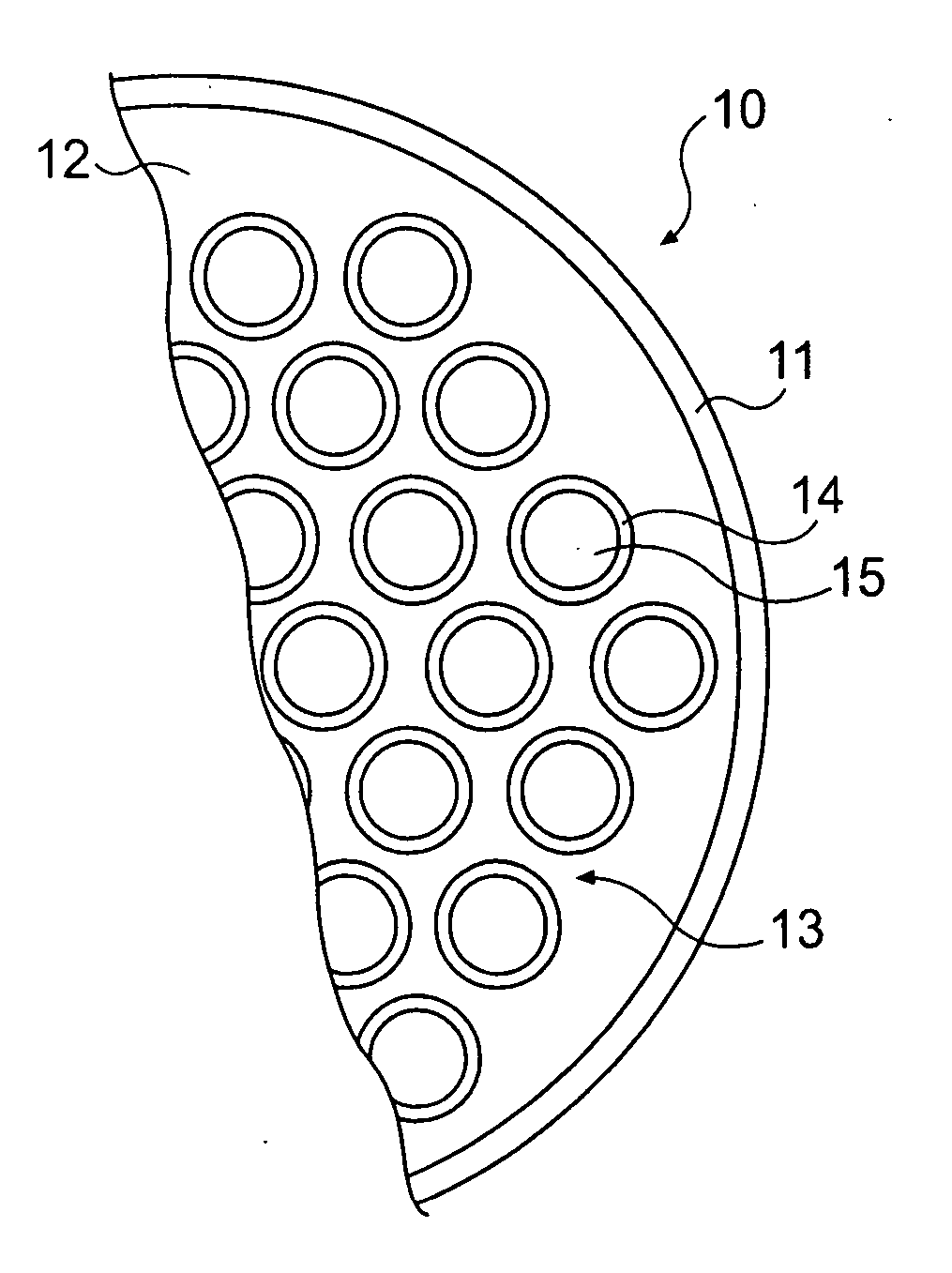
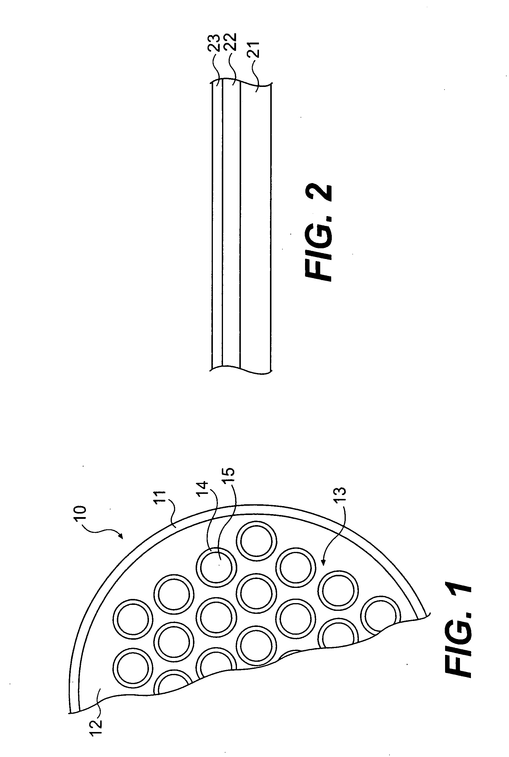
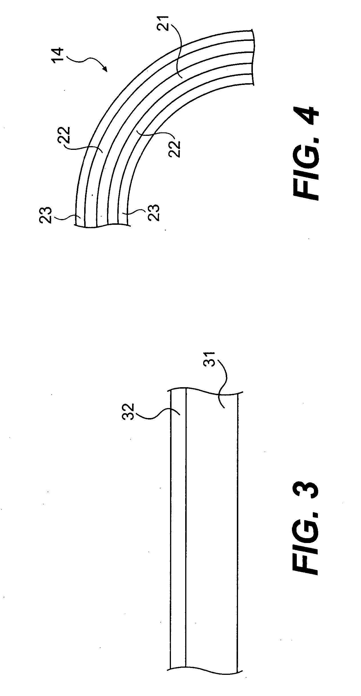
[0033] The present invention will now be described in greater detail in connection with the attached figures. FIG. 1 is a tube-in-shell heat exchanger 10, which is located upstream from a furnace (not shown) and employs the principles of the present invention. The tube-in-shell heat exchanger 10 disclosed herein illustrates one application of the present invention to reduce sulfidation or sulfidic corrosion and depositional fouling in refinery and petrochemical applications. The tube-in-shell exchanger 10 is just one heat transfer component falling under the scope of the corrosion reduction and fouling mitigation measures in accordance with the present invention. The principles of the present invention are intended to used in other heat exchangers including but not limited to spiral heat exchangers, tube-in-tube heat exchangers and plate-and-frame heat exchangers having at least one heat transfer element. The principles of the present invention are intended to be employed in other h...


PUM

PropertyMeasurementUnit
temperaturesaaaaaaaaaa

Abstract

A method and device for reducing sulfidation corrosion and depositional fouling in heat transfer components within a refining or petrochemical facility is disclosed. The heat transfer components are formed from a corrosion and fouling resistant steel composition containing a Cr-enriched layer and having a surface roughness of less than 40 micro inches (1.1 μm).

Description

CROSS REFERENCE TO RELATED APPLICATION [0001] This application relates to and claims priority to U.S. Provisional Patent Application No. 60 / 751,985, filed Dec. 21, 2005, entitled “Corrosion Resistant Material For Reduced Fouling, A Heat Exchanger Having Reduced Fouling And A Method For Reducing Heat Exchanger Fouling in a Refinery,” the disclosure of which is hereby specifically incorporated by reference.FIELD OF THE INVENTION [0002] This invention relates to the reduction of sulfidation or sulfidic corrosion and the reduction of depositional fouling in general and in particular the reduction of sulfidation or sulfidic corrosion and the reduction of depositional fouling in heat transfer components, which include but are not limited to heat exchangers, furnaces and furnace tubes located in refining facilities and petrochemical processing facilities. In particular, the present invention relates to the reduction of corrosion and fouling associated with heat transfer components used in ...

Claims


Application Information

Patent Timeline
Patent Type & Authority Applications(United States)
IPC IPC(8): F28F19/02
CPCF28F19/06Y10T29/49352Y10T428/12472
Inventor GREANEY, MARK A.BRUNO, THOMASCOOPER, ASHLEY E.CODY, IAN A.CHUN, CHANGMIN
Owner EXXON RES & ENG CO
Why Eureka
Try Eureka