Resin composite copper foil, printed wiring board, and production processes thereof

a technology of printed wiring boards and composite copper foils, which is applied in the direction of resistive material coating, synthetic resin layered products, metallic material coating processes, etc., can solve the problems of obstructing the formation of ultra-fine lines, reducing the location accuracy or adhesive strength of the circuit, and lack of adhesive strength of the fine circuit, etc., to achieve excellent heat resistance and heat resistance, excellent adhesive strength, and small roughness

Active Publication Date: 2007-07-26
MITSUBISHI GAS CHEM CO INC
View PDF6 Cites 24 Cited by
  • Summary
  • Abstract
  • Description
  • Claims
  • Application Information

AI Technical Summary

Benefits of technology

[0021]The resin composite copper foil obtained by the present invention is excellent in adhesive strength so that a copper foil having a surface with extremely small roughness can be used. By using the above resin composite copper foil, a copper-clad laminate excellent in heat resistance and heat resistance after moisture absorption can be obtained. This copper-clad laminate is suitably used as a high-density printed wiring board having a fine circuit so that the industrial utilities of the resin composite copper foil and the process for the production of the resin composite copper foil, provided by the present invention, are remarkably high.
[0022]A printed wiring board obtained by the process of the production of a printed wiring board, provided by the present invention, enables an ultra-fine line (approximately 12 μm in width) copper circuit to be formed. The above circuit width is remarkably smaller than a conventional fine line circuit width. Further, the above printed wiring board is excellent in adhesive strength and heat resistance after moisture absorption. Therefore, the above printed wiring board is suitable as a high-density printed wiring board having a fine circuit, and the practical utilities of the technology of the present invention are remarkably high.

Problems solved by technology

When an etching time is prolonged for removing the remaining convex portions completely, the circuit is etched too much so that the location accuracy or adhesive strength of the circuit is decreased.
When these copper foils are used for copper-clad laminates of high-heat-resistant thermosetting resins, etc., which basically have a weak adhesive strength, the lack of adhesive strength is a problem about fine circuits.
This greatly obstructs the formation of ultra-fine lines.
Copper-clad laminates using such adhesive agent-attached copper foils have problems in terms of the degree of adhesive strength or heat resistance after moisture absorption.

Method used


Image

  • Resin composite copper foil, printed wiring board, and production processes thereof
  • Resin composite copper foil, printed wiring board, and production processes thereof
  • Resin composite copper foil, printed wiring board, and production processes thereof

Examples


examples

[0052]The present invention will be specifically explained with reference to Synthetic Example, Comparative Synthetic Example, Examples and Comparative Examples, hereinafter.

Synthetic Example

[0053]A 2-liter three-necked flask having an anchor type stirring rod made of stainless steel, a trap equipped with a nitrogen-introducing tube and a stopcock, and a reflux condenser having a cooling tube with a ball, installed on the trap, was charged with 117.68 g (400 mmol) of 3,4,3′,4′-biphenyltetracarboxylic dianhydride, 87.7 g (300 mmol) of 1,3-bis(3-aminophenoxy)benzene, 4.0 g (40 mmol) of γ-valerolactone, 4.8 g (60 mmol) of pyridine, 300 g of N-methyl-2-pyrrolidone (to be referred to as “NMP” hereinafter) and 20 g of toluene. The mixture was heated at 180° C. for 1 hour and then cooled down to about room temperature. 29.42 g (100 mmol) of 3,4,3′,4′-biphenyltetracarboxylic dianhydride, 82.12 g (200 mmol) of 2,2-bis{4-(4-aminophenoxy)phenyl}propane, 200 g of NMP and 40 g of toluene were ad...

examples 1-4

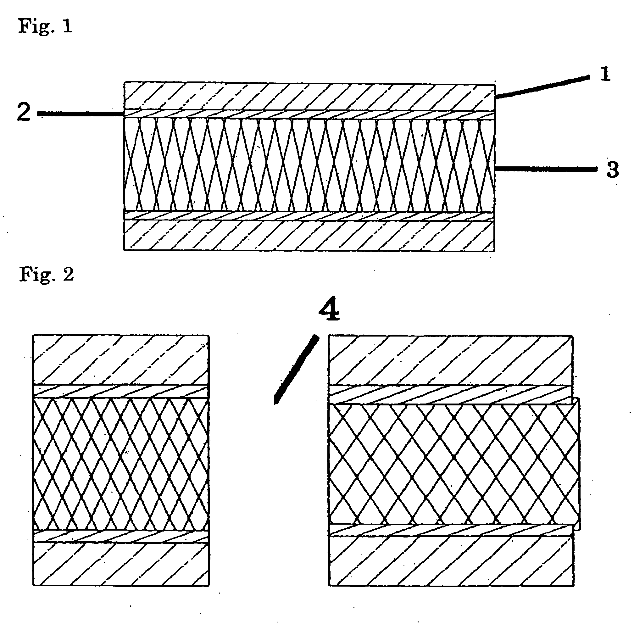
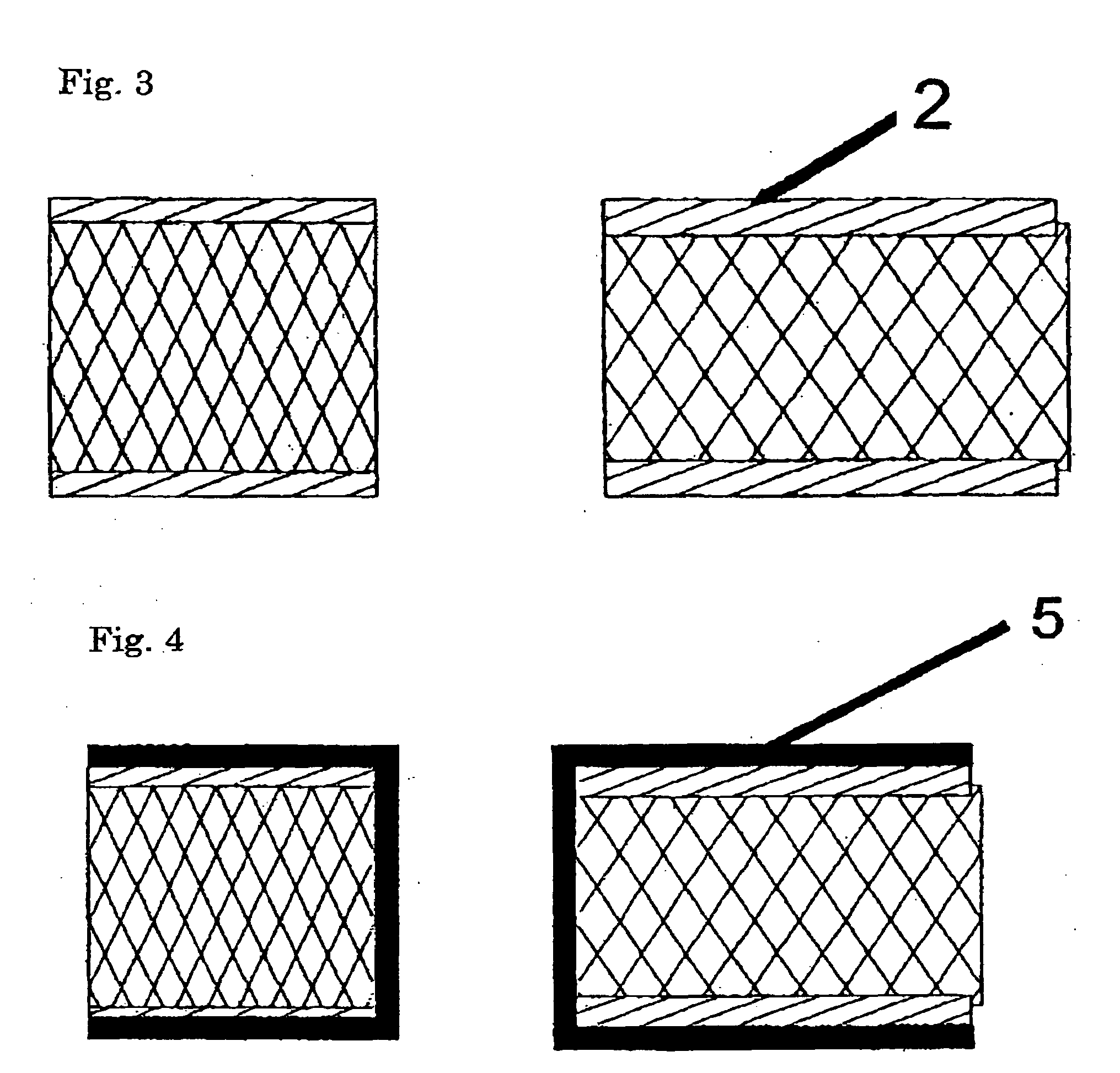
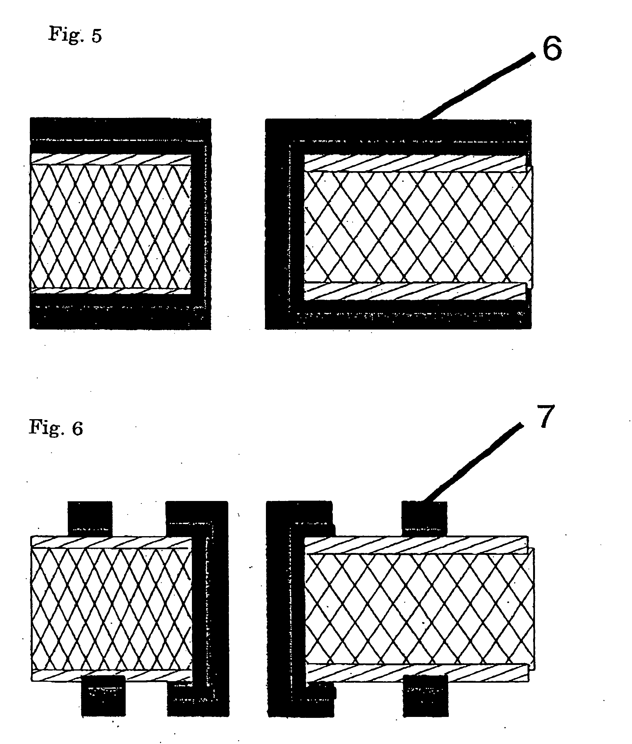
[0055]The block copolymer polyimide solution obtained in Synthetic Example was further diluted with NMP to prepare a block copolymer polyimide solution having a solid content of 10%. This block copolymer polyimide solution and bis(4-maleimidophenyl)methane (BMI-H, supplied by K I KASEI KK) were molten and mixed at 60° C. for 20 minutes in accordance with solid content weight ratios shown in Table 1, thereby preparing resin solutions respectively. The thus-prepared resin solutions were respectively applied to a mat surface of an electrolytic copper foil (F0-WS foil, Rz=1.5 μm, supplied by Furukawa circuit foil Co., Ltd.) having a thickness of 12 μm with a reverse roll coating machine, then dried under a nitrogen atmosphere at 120° C. for 3 minutes and 160° C. for 3 minutes and then lastly heat-treated at 300° C. for 2 minutes, thereby preparing resin composite copper foils respectively. On the other hand, 400 g of 2,2-bis(4-cyanatophenyl)propane was molten at 150° C. and allowed to r...

example 5

[0056]A resin composite copper foil and a copper-clad laminate were produced in the same manner as in Example 3 except that a resin solution was prepared by using 2,2-bis[4-(4-maleimidophenoxy)phenyl]propane (BMI-80, supplied by K I KASEI KK) in place of bis(4-maleimidophenyl)methane used in Example 3. Table 1 shows the evaluation results.

TABLE 1Evaluation ResultsEx. 1Ex. 2Ex. 3Ex. 4Ex. 5ResinBlock copolymer8065502550compositepolyimidecopperMaleimide20355075—foilcompound BMI-HMaleimide————50compound BMI-80Total thickness1615151515(μm)Copper foil adhesive strength1.291.441.731.751.73(kg / cm)Heat240° C. treatment∘∘∘∘∘∘∘∘∘∘∘∘∘∘∘resistance280° C. treatment∘∘x∘∘∘∘∘∘∘∘∘∘∘∘in airHeat1 hour∘∘∘∘∘∘∘∘∘∘∘∘∘∘∘resistance3 hours∘∘∘∘∘∘∘∘∘∘∘∘∘∘∘after5 hours∘∘∘∘∘∘∘∘∘∘∘∘∘∘∘moisture7 hours∘∘∘∘∘∘∘∘∘∘∘∘∘∘∘absorptionEx. = Example


PUM

PropertyMeasurementUnit
thicknessaaaaaaaaaa
widthaaaaaaaaaa
temperatureaaaaaaaaaa

Abstract

A resin composite copper foil comprising a copper foil and a resin layer containing a block copolymer polyimide and a maleimide compound, the resin layer being formed on one surface of the copper foil, a production process thereof, a copper-clad laminate using the resin composite copper foil, a production process of a printed wiring board using the copper-clad laminate, and a printed wiring board obtained by the above process.

Description

FIELD OF THE INVENTION[0001]The present invention relates to a resin composite copper foil used for printed wiring boards, a process for the production of the resin composite copper foil, a copper-clad laminate using the resin composite copper foil, a printed wiring board using the copper-clad laminate and a process for the production of the printed wiring board. The resin composite copper foil obtained by the present invention is excellent in adhesive strength so that a copper foil having a surface with extremely small roughness can be used. The copper-clad laminate using the above resin composite copper foil is suitably used as a high-density printed wiring board having fine circuits. Further, a printed wiring board obtained by the process of the present invention is excellent in adhesive strength of a copper plating layer or heat resistance so that the printed wiring board is suitably used as a high-density printed wiring board having fine circuits.BACKGROUND OF THE INVENTION[000...

Claims


Application Information

Patent Timeline
Patent Type & Authority Applications(United States)
IPC IPC(8): B32B15/08
CPCC08G73/1042C08G73/12H05K3/181H05K3/386H05K2201/0154H05K2201/0358Y10S428/901B32B7/06B32B15/14B32B15/20B32B27/281B32B27/38H05K2203/1152Y10T428/31681Y10T428/31721B32B15/08
Inventor NOZAKI, MITSURUGAKU, MORIOTANAKA, YASUONAGATA, EIJIKIKUCHI, YASUOYANO, MASASHI
Owner MITSUBISHI GAS CHEM CO INC
Why Eureka
Try Eureka