
Organic electroluminescent device

a technology of electroluminescent devices and organic el, which is applied in the direction of discharge tube luminescnet screens, natural mineral layered products, transportation and packaging, etc., can solve the problems of inability to quantitatively prove the effect of impurities in a practical phosphorescent organic el device, and the structure and properties of the effect of the organic el device not yet shown clearly, etc., to achieve high emission luminance and high luminous efficiency

Active Publication Date: 2007-07-26
IDEMITSU KOSAN CO LTD
View PDF9 Cites 57 Cited by
  • Summary
  • Abstract
  • Description
  • Claims
  • Application Information

AI Technical Summary

Benefits of technology

The present invention provides an organic EL device with high emission luminance and efficiency, and a long life. This is achieved by reducing the concentration of halogen elements as impurities in the material for the organic EL device. The invention also provides a phosphorescent organic metal complex and a host material for the organic EL device, as well as a method for identifying and reducing halogen element concentrations in the material. The organic EL device comprises a phosphorescence light-emitting layer containing at least a host material and a phosphorescent organic metal complex. The invention solves the problem of halogen element concentration in the light-emitting layer of a phosphorescent organic EL device and improves its performance.

Problems solved by technology

However, not only effects exerted on the performances of the organic EL device by the structures and the properties of the compounds have not been clearly shown, but also a method for making it quantitatively clear has not yet been established.
However, a case containing a phosphorescent material is not described in the patent document 3, and a quantitative effect of impurities in a practical phosphorescent organic EL device has never been referred to and is uncertain.
However, the resolution is deteriorated when a concentration of the impurities is low, and accurate quantitative determination is limited.
It is confirmed by high performance liquid chromatography (HPLC) that materials used for the above device have a purity of 99.9% or more, but it is shown that limitation in detection of an impurity concentration is 0.1 mass % (1000 ppm).
However, it is not described therein that a halogen concentration exerts an effect directly on the device performances, and it is not described as well that it was detected by using a method for detecting directly halogens.
Further, the whole mass concentration of halogens contained in materials containing free halogens is not analyzed, and therefore an amount of halogens contained in the iridium complex is not measured, so that a true chlorine concentration is uncertain.
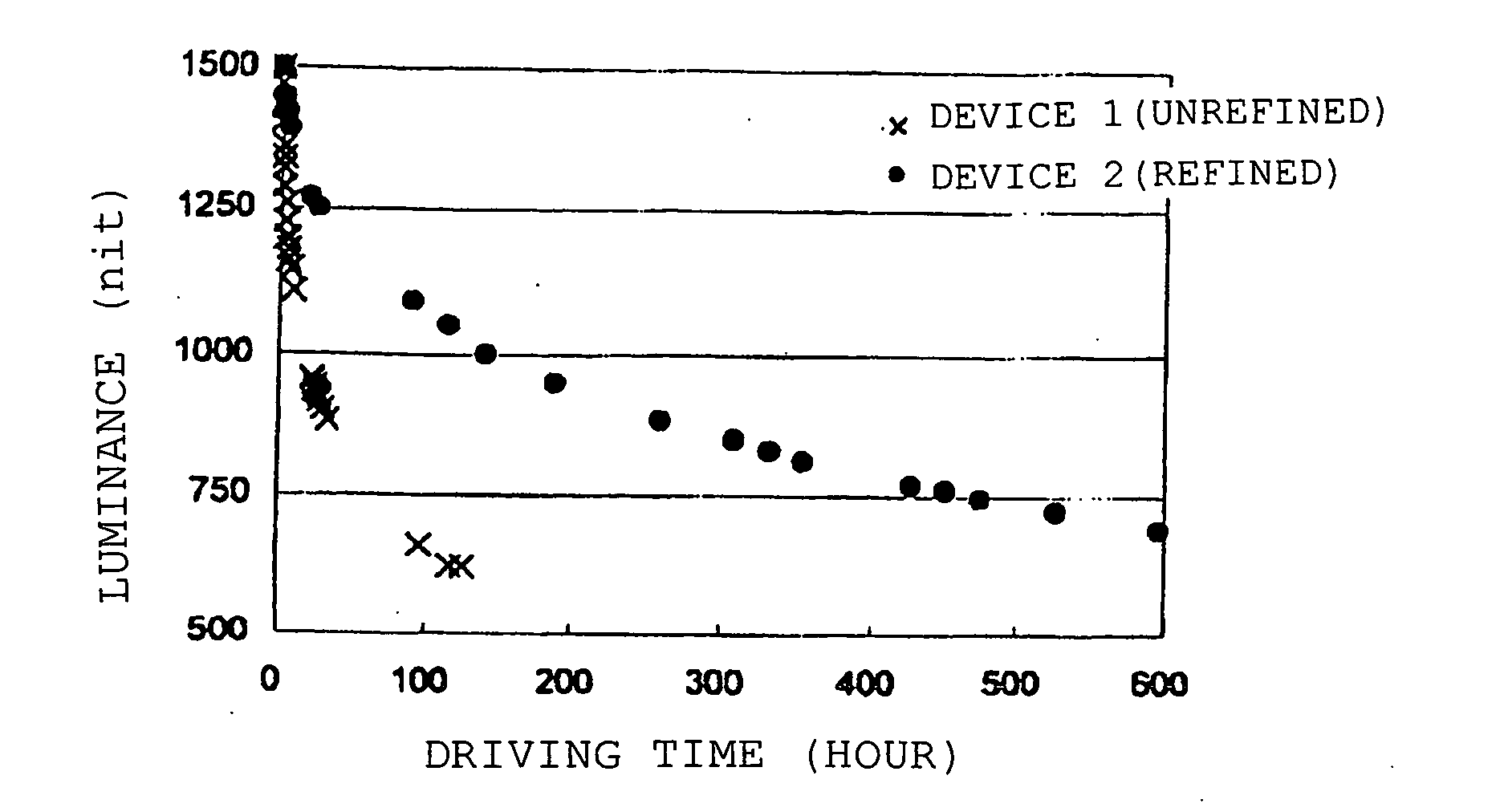
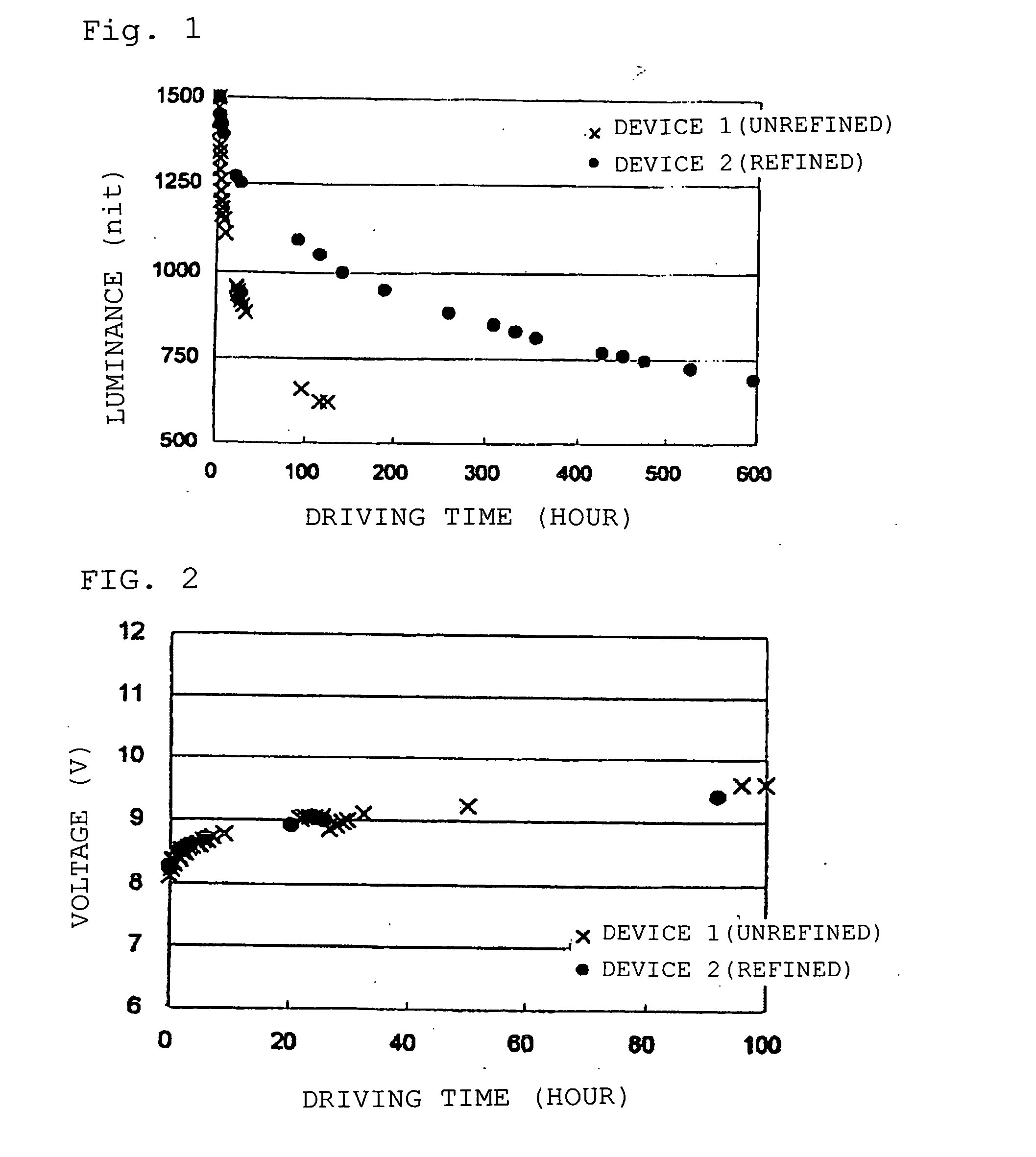
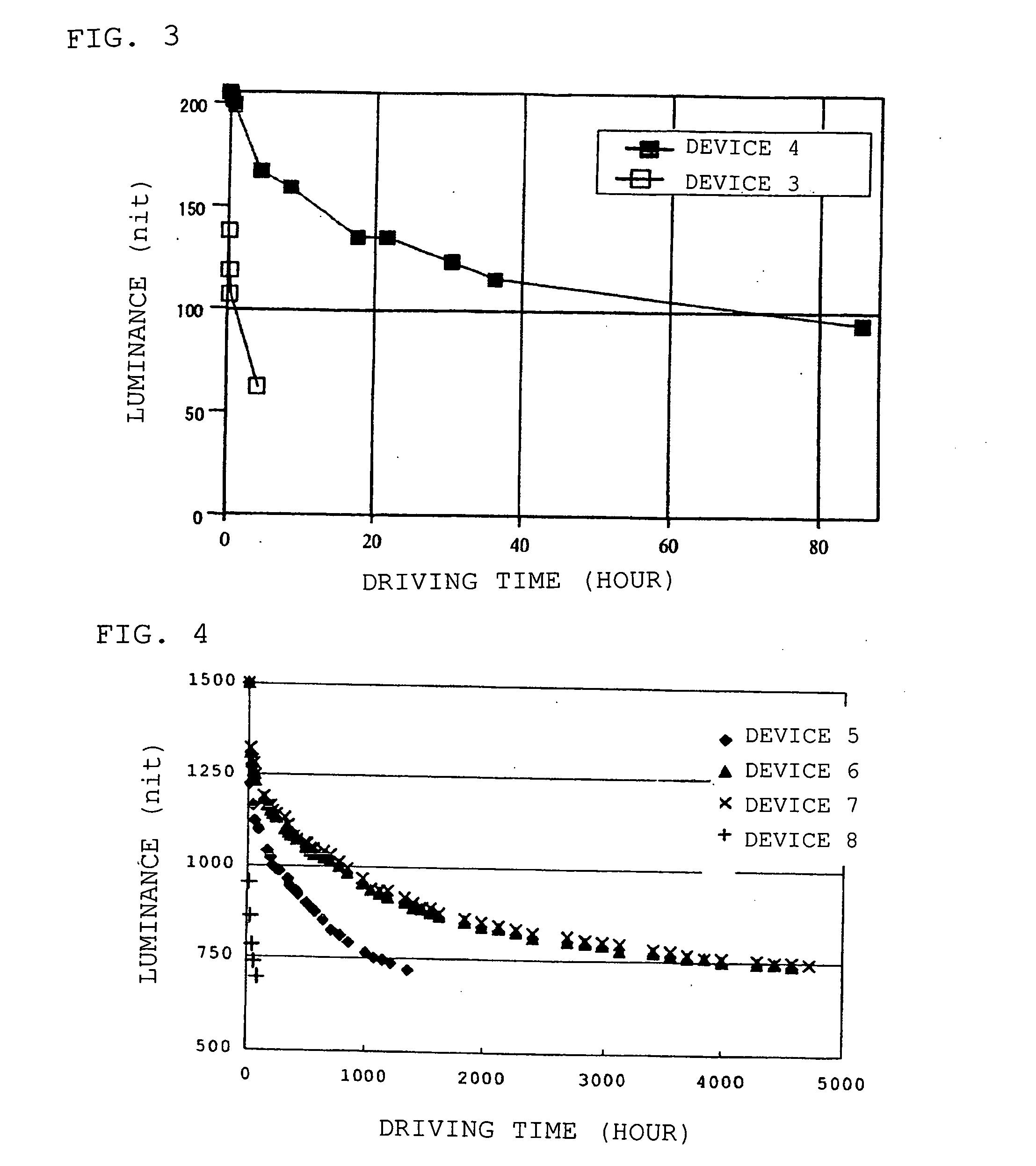
In the case of a phosphorescent organic electroluminescent device, a high luminous efficiency is expected, and therefore deterioration caused by applying an electric current is a serious problem.

Method used


Image

  • Organic electroluminescent device
  • Organic electroluminescent device
  • Organic electroluminescent device

Examples


example 1

and the Comparative example 1

[0129] A luminescent material 1 (hereinafter referred to as the [Host 1]) was synthesized according to a synthetic scheme shown below:

[0130] The compound [Host 1] was synthesized in the following manner.

Synthesis of Synthetic Intermediate (1)

[0131] Dissolved in 200 ml of methanol were 18.0 g (68 mmol) of 3,5-dibromobenzaldehyde and 9.0 g (75 mmol) of acetophenone, and 70 ml (70 mmol) of a 1M sodium hydroxide aqueous solution was dropwise added thereto, followed by stirring the solution at room temperature for 30 minutes. After finishing the reaction, crystal deposited was filtered and washed with methanol to obtain 20.4 g (yield: 82%) of a synthetic intermediate (1).

Synthesis of Synthetic Intermediate (2)

[0132] Suspended in 70 ml of ethanol were 10.0 g (27 mmol) of the synthetic intermediate (1) and 4.4 g (28 mmol) of benzamidine hydrochloride, and 3.3 g (60 mmol) of sodium hydroxide was added thereto, followed by heating and refluxing the soluti...

example 2

and the Comparative Example 2

[0151] A luminescent material 2 (hereinafter referred to as the [Host 2]) was synthesized according to a synthetic scheme shown below:

[0152] The compound [Host 2] was synthesized in the following manner.

Synthesis of Synthetic Intermediate (3)

[0153] Suspended in 50 ml of 1,4-dioxane were 5.0 g (16 mmol) of 1,3,5-tribromobenzene, 5.3 g (31 mmol) of 1,2,3,4-tetrahydrocarbazole, 0.3 g (0.4 mmol) of copper iodide and 13.8 g (65 mmol) of potassium phosphate, and 1.9 ml (16 mmol) of trans-1,2-cyclohexanediamine was added thereto. The mixture was heated and refluxed for 26 hours under argon atmosphere. The reaction solution was cooled down to room temperature, and methylene chloride and water were added thereto to separate the solution into two layers. Then, the organic layer separated was washed with water and dried on anhydrous sodium sulfate. After distilling the organic solvent off under reduced pressure, the residue was refined by silica gel chromatogr...


PUM

PropertyMeasurementUnit
pressureaaaaaaaaaa
triplet energy gapaaaaaaaaaa

Abstract

Provided is an organic electroluminescent device in which an organic thin film layer comprising a single layer or plural layers comprising a phosphorescence light-emitting layer containing at least a host material and a phosphorescent organic metal complex is interposed between a cathode and an anode, wherein the total of the halogen element mass concentrations of bromine, iodine and chlorine which are contained as impurities in the host material constituting the light-emitting layer described above is 50 ppm or less. It has a high emission luminance, a high luminous efficiency and a long life.

Description

BACKGROUND OF THE INVENTION [0001] The present invention relates to an organic electroluminescent device comprising a phosphorescent organic thin film layer and a material for an organic electroluminescent device, specifically to an organic electroluminescent device having a high emission luminance and a high luminous efficiency and having a long life, a material for an organic electroluminescent device, a luminescent organic metal complex and a host material for an organic electroluminescent device. RELATED ART [0002] An organic electroluminescent device (hereinafter “electroluminescent” shall be abbreviated as EL) is a spontaneous luminescent device making use of the principle that a fluorescent substance emits light by recombination energy of holes injected from an anode and electrons injected from a cathode by applying an electric field. Since a low voltage-driven organic EL device of a laminate type was reported by C. W. Tang of Eastman Kodak Company (C. W. Tang and S. A. Vansl...

Claims


Application Information

Patent Timeline
Patent Type & Authority Applications(United States)
IPC IPC(8): H01L51/54H01L51/56C09K11/06H01L51/50H05B33/14H05B33/22
CPCC09K11/06C09K2211/1029C09K2211/1037C09K2211/1044C09K2211/1059Y10T428/265H01L51/5016H05B33/14H05B33/22Y10S428/917C09K2211/185Y10T428/31504H10K50/11H10K2101/10H10K10/29
Inventor IWAKUMA, TOSHIHIROYASUDA, HIROYAIKEDA, KIYOSHIYAMAMICHI, KEIKOARAKANE, TAKASHIHOSOKAWA, CHISHIO
Owner IDEMITSU KOSAN CO LTD
Learn More