Implant and method of producing the same, and a system for implantation

a technology of implant and method, applied in the field of coating implants, can solve the problems of increasing the risk of implant loosening, and achieve the effect of promoting bone regrowth and high strength

Inactive Publication Date: 2007-07-26
DOXA AB
View PDF4 Cites 24 Cited by
  • Summary
  • Abstract
  • Description
  • Claims
  • Application Information

AI Technical Summary

Benefits of technology

[0005] In view of the prior art implants for use in contact with biological tissue, particularly when anchoring implants in bone, there is a need for an implant and implant anchoring t

Problems solved by technology

Even small gaps may lead to small movements, micromotions, between implant and the tissue, which increase the risk of implant loosening, e.g. due to formation of zones of fibro

Method used


Image

  • Implant and method of producing the same, and a system for implantation
  • Implant and method of producing the same, and a system for implantation
  • Implant and method of producing the same, and a system for implantation

Examples


example 1

[0055] Titanium dental screw implants with a diameter of 3.70 mm and having a thread length of 5 mm were implanted in the tibia condyl of adult rabbits. These screws, mildly sand-blasted, were used as reference screws (Series D below). Holes were drilled following a dental implantation procedure involving two drilling steps using tools with a greater diameter than that of the implant, followed by creation of threaded holes into which all implants were screwed to the same depth.

[0056] Other implant screws, of the same type as the references screws (mildly sand-blasted), were plasma-sprayed, with a calcium aluminate, CaO.Al2O3, (Series A) and calcium silicate, CaO.SiO2 (Series B). Both series were sprayed such that they generated a surface coating having a thickness of about 30 microns on the threaded section. A third series C, were RF-sputtered with a thin CA-coating (approximately 0.2 μm and covered with a thin water-based calcium aluminate paste (having the same composition as use...

example 2

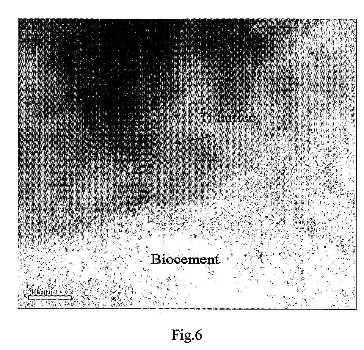
[0059] A transmission electron microscopy (TEM) study of the hydrate grain size was performed on plasma-sprayed coatings of hydrated CaOAl2O3.

[0060] Metallic implants were put in the femur of rabbits for 24 h. The rabbits were then terminated and the implant fixated and embedded. To obtain TEM samples of the hydrated coatings, focused ion beam microscopy (FIB) was used. Cross-sections of the metal-coating interface were produced via cutting with a diamond saw and polished to 0,25 micron using a cloth and diamond paste. TEM-samples of five by five micron were produced from the cross-sections using the FIB. The samples were then imaged in annular dark field STEM mode in a 200 keV FEG TEM (Jeol).

[0061] The hydrates were plate- or needle-shaped and had a grain size of below 100 nm, see FIG. 7.

example 3

[0062] A chemically active surface was produced on an inert alumina implant by pressing a layer of CaOAl2O3 onto the alumina surface, followed by a heat treatment at 1100° C. for 6 h. Examination of the surface composition after heat treatment with X-ray diffraction, showed that only crystalline CaOAl2O3 was present on the surface. The adhesion between the CaOAl2O3 layer and the implant was very strong as tested with scratch testing, and no delamination of the coating occurred.


PUM

PropertyMeasurementUnit
Lengthaaaaaaaaaa
Lengthaaaaaaaaaa
Fractionaaaaaaaaaa

Abstract

The present invention relates to a coated implant for in vivo-anchoring of implants to a biological tissue or another implant, which coated implant comprises an implant having a pre-treated surface and on said pre-treated surface one or more layers of ceramic material chemically and/or mechanically bound to said pre-treated surface. Said one or more layers comprises mainly non-hydrated chemically bonded ceramic material, and each layer independently comprises a first binder phase selected from the group consisting of aluminates, silicates, phosphates, sulphates and combinations thereof. The invention further relates to method of manufacturing said coated implant, a ceramic paste and to a kit comprising said coated implant and ceramic paste. The invention is particularly suitable for dental and orthopaedic implants.

Description

TECHNICAL FIELD [0001] The present invention relates to a coated implant for in vivo-anchoring of implants to a biological tissue or another implant, which coated implant comprises an implant having a pre-treated surface and on said pre-treated surface one or more layers of ceramic material chemically and / or mechanically bound to said pre-treated surface. The invention further relates to method of manufacturing said coated implant, and to a kit comprising said coated implant and a ceramic paste comprising a calcium-based binder. The invention is particularly suitable for dental and orthopaedic implants. STATE OF THE ART AND PROBLEM [0002] For implants that are to interact with the human implant, it is an advantage with implant materials that due to their biocompatibility provide an optimal fixation or anchoring of the implant to the biological tissue, e.g. bone. Even small gaps may lead to small movements, micromotions, between implant and the tissue, which increase the risk of impl...

Claims


Application Information

Patent Timeline
IPC IPC(8): A61F2/02A61K6/06A61L27/30C04B35/22C04B35/44C04B41/50C04B41/85
CPCA61L27/306B82Y30/00C04B2235/781C04B2235/3205C04B2111/00836C04B35/22C04B35/44C04B41/009C04B41/5024C04B41/5032C04B41/85C04B35/10C04B35/48A61K6/0631
Inventor HERMANSSON, LEIFENGQVIST, HAKANLOOF, JESPER
Owner DOXA AB
Why Eureka
Try Eureka