Bulk solidified quenched material and process for producing the same

a technology of quenched material and bulk solidification, which is applied in the direction of magnetic materials, magnetic bodies, device material selection, etc., can solve the problems of difficult to obtain a material having predetermined properties by a melt method, and achieve the effect of increasing the energy density of rising strain at the initial magnetization stage, superior workability (ductility), and high rigidity

Inactive Publication Date: 2007-08-09
JAPAN SCI & TECH CORP
View PDF1 Cites 20 Cited by
  • Summary
  • Abstract
  • Description
  • Claims
  • Application Information

AI Technical Summary

Benefits of technology

[0025] The new bulk rapidly solidified Fe—Ga magnetostrictive alloy according to the present invention can obtain approximately 80% of magnetostriction of a single crystalline magnetostrictive alloy, is significantly inexpensive (approximately one twentieth) as compared to the conventional rare earth-based Tefenol-D, and also has superior workability (ductility) and high rigidity. Accordingly, a rising strain energy density at an initial magnetization stage can be increased. In addition, the bulk Ti—Ni-based shape-memory alloy can be formed into a large bulk material having improved performances as compared to that of an arc melted and processed material used as a starting material, such as a narrow transformation point width and a high mechanical strength (hardness) 1.4 times or more than that of the arc melted and processed material. In addition, according to the method of the present invention, rapidly solidified materials can be formed into a bulk shape by a mass production process.

Problems solved by technology

However, an alloy having high performances as described above has been realized primarily by a thin belt or a thin wire having a thickness or a diameter of approximately 200 μm or less, and it has been difficult to obtain a material having predetermined properties by a melt method.

Method used


Image

  • Bulk solidified quenched material and process for producing the same
  • Bulk solidified quenched material and process for producing the same
  • Bulk solidified quenched material and process for producing the same

Examples


example 1

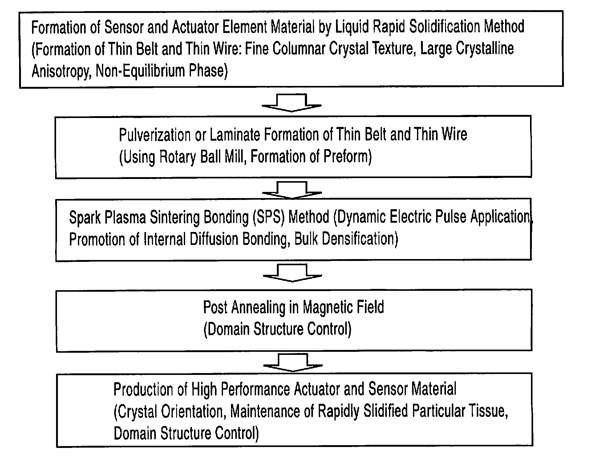
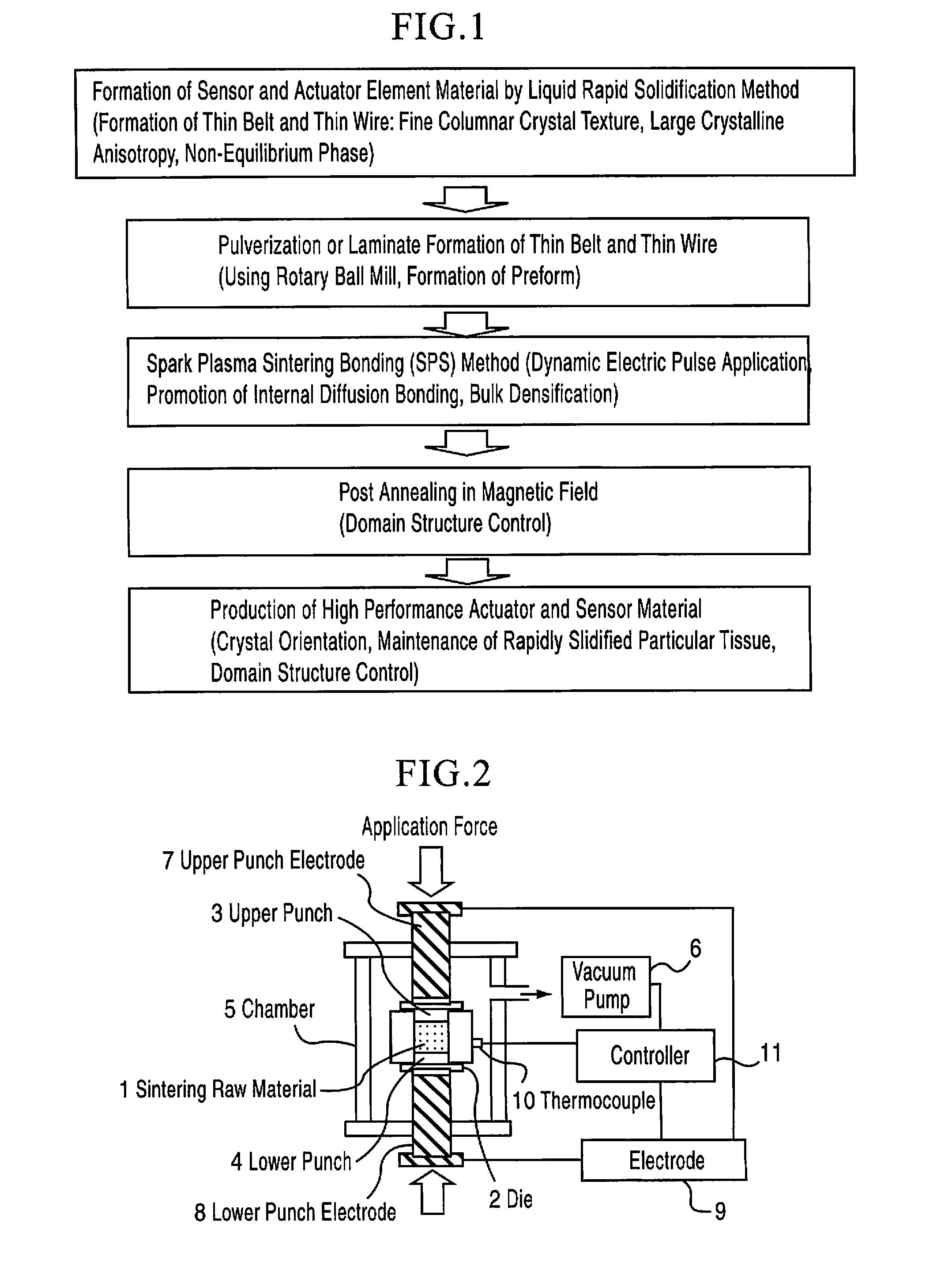
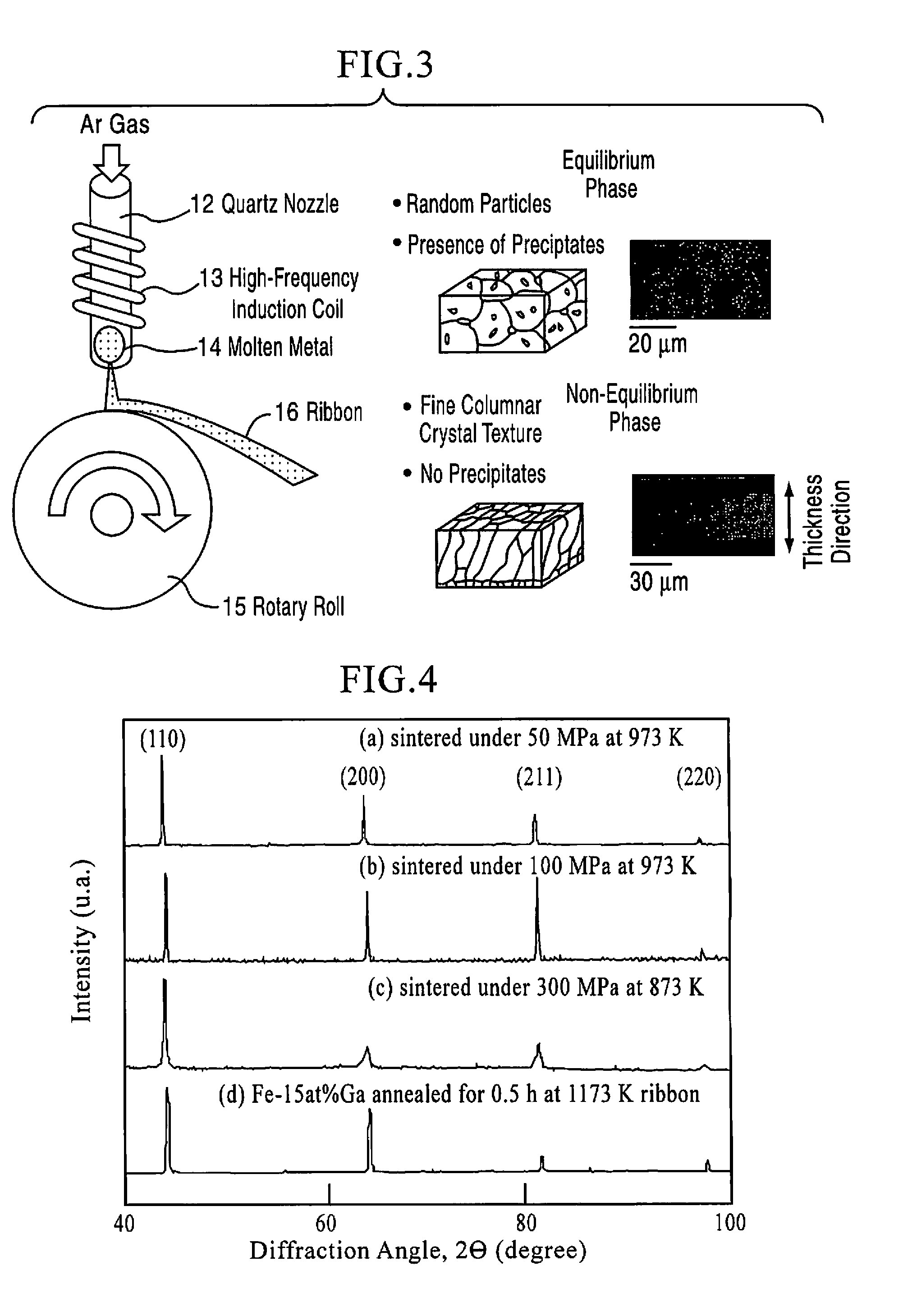
[0045] A Fe-17 at % Ga alloy ingot was formed by melting electrolytic iron and Ga by a plasma arc melting method. This ingot was melt and was formed into a thin belt 2 m long, 5 mm wide, and 80 μm thick in an argon atmosphere by a liquid rapid solidification (single roll) method. This thin belt was cut into slices 40 mm long to be used for a discharge plasma sintering sample.

[0046] After 300 slices were stacked together in a cemented carbide alloy die, sintering was performed for Sample (a) under 50 MPa at 973 K, Sample (b) under 100 MPa at 973 K, and Sample (c) under 300 MPa at 873 K, and the sintering time was set to 5 minutes. As a spark plasma sintering apparatus, SPS 1050 manufactured by Sumitomo Coal Mining Co., Ltd. was used. The spark plasma sintering was performed at a vacuum degree of 2 Pa, a current of 3,000 A, and a voltage of 200 V. The temperature rising conditions were different depending on the temperature; however, it was approximately 30 minutes. The size of the s...

example 2

[0052] Sample (b), the sample sintered under 100 MPa at 973 K, produced by the method described in Example 1 was annealed at 1,173 K for 1 hour in a vacuum atmosphere. After the annealing, the magnetostriction was measured. FIG. 7 is a graph showing the magnetostrictions of the sintered sample before and after the annealing. The magnetostrictions before and after the annealing at H of 2 kOe were 100 ppm and 170 to 230 ppm, respectively, and it was found that the magnetostriction was increased by the annealing. Furthermore, when annealing in a magnetic field was performed after the sintering, the magnetostriction was increased to 250 to 260 ppm. The reason the magnetostriction is increased when the thin belt sample is annealed for a short period of time is believed that the [100] orientation is enhanced so that the magnetostriction is increased [see Non-Patent Document 2], and in addition, it is also believed that the magnetic moments (magnetic domain structures) directly relating to...

example 3

[0053] [Example of TiNiCu Shape-Memory Alloy]

[0054] Materials were weighed so as to have a composition of Ti50Ni40Cu10 (atomic percent) and were then formed into alloy ingots as a raw material by a plasma arc melting method in an argon atmosphere. Subsequently, from the ingots thus formed, a thin belt (ribbon) was formed by a high frequency induction melting-liquid rapid solidification method (twin roll quenching method), and a thin wire (fiber) was formed by plasma arc melting-melt extraction rapid solidification method (conical-roll front-end spinning method), so that rapidly solidified materials were obtained. The rapidly solidified materials were wet-pulverized (in ethanol having a purity of 99.99%) by ball milling, so that Example A (ribbon) and Example B (fiber) were obtained. In addition, pulverization was performed in a dry atmosphere (in the air), so that Comparative example A (ribbon) and Comparative example B (fiber) were obtained.

[0055] The DSC change with the milling t...


PUM

PropertyMeasurementUnit
temperatureaaaaaaaaaa
pressureaaaaaaaaaa
diameteraaaaaaaaaa

Abstract

[Object] A bulk material which is suitably used as a material for actuator and sensor elements is formed from a Fe—Ga base magnetoresistive alloy and a Ti—Ni base shape memory alloy taking advantage of crystal miniaturization and anisotropy as well as reduction of precipitates (equilibrium state in state diagram) and non-equilibrium phases peculiar to liquid rapidly solidified materials, and the performance of the material is enhanced by a production method thereof which has cost advantage over a melt method.
[Construction] A rapidly solidified material having a particular rapidly solidified texture of a Fe—Ga magnetostrictive alloy or a TiNi-based shape-memory alloy and properties derived therefrom is formed into slices which are laminated to each other in a die, or is formed into a powder or chops which are filled in the die. Subsequently, spark plasma sintering is performed so that bonds between the slices, grains of the powder, or the chops are formed at a high density to form a bulk alloy, followed by annealing whenever necessary, so that the properties of the alloy are improved.

Description

TECHNICAL FIELD [0001] The present invention relates to a rapidly solidified material consolidated into a bulk form and a method for producing the same, and more particularly, relates to a giant magnetostrictive alloy or a shape-memory alloy and a method for producing the same, the alloy being a bulk rapidly solidified material which is produced by a liquid rapid solidification method and a spark plasma sintering method and which is used as a material for sensor and actuator elements. BACKGROUND ART [0002] By using a liquid rapid solidification method, various amorphous, fine crystalline, and polycrystalline alloy-based materials have been developed. Functional materials, such as a shape-memory alloy, in the form of a thin belt, a thin wire, and a powder can be formed by a liquid rapid solidification method (Patent Documents 1 and 2). [0003] As for an iron-based magnetic shape-memory alloy, one (Furuya) of the inventors of the present invention found a giant magnetostrictive effect ...

Claims


Application Information

Patent Timeline
Patent Type & Authority Applications(United States)
IPC IPC(8): B22F3/105C22C14/00H01F1/08B22F3/14B22F9/04C22C1/04C22C19/03C22C33/02C22C38/00H01L41/20H01L41/22H01L41/47
CPCB22F9/008B22F2003/248C22F1/183C22F1/006C22C33/0278C22C14/00C22C1/0458B22F2998/10B22F2998/00B22F2009/043B22F2009/041B22F3/14B22F3/105B22F2202/13B22F2201/11B22F9/04B22F3/24
Inventor FURUYA, YASUBUMIOKAZAKI, TEIKOSAITO, CHIHIROYOKOYAMA, MASAKIOOMORI, MAMORU
Owner JAPAN SCI & TECH CORP
Why Eureka
Try Eureka