Method for fluorescence lifetime imaging microscopy and spectroscopy

a lifetime imaging and fluorescence technology, applied in the field of fluorescence lifetime imaging microscopy and spectroscopy, can solve the problems of insufficiently analyzing the time-resolved fluorescence decay transient in terms of multi-exponential decay, time-consuming iterative methods for recovering time decays, and inability to meet the requirements of a short excitation pulse and a single exponential fluorescence decay in practice, etc., to achieve less expensive and complex flim

Active Publication Date: 2007-08-23
CEDARS SINAI MEDICAL CENT
View PDF4 Cites 43 Cited by
  • Summary
  • Abstract
  • Description
  • Claims
  • Application Information

AI Technical Summary

Benefits of technology

[0015] This method provides several advantages over current algorithms for time resolved fluorescence imaging. By way of example, the intrinsic fluorescence intensity decays of any form can be estimated at every pixel as an expansion on a Laguerre basis, without a priori assumption of their functional form. Additionally, the number of images required to expand the fluorescence IRF from each pixel is significantly low, thus allowing the reduction of the acquisition time. In one embodiment, the number of images required may be as few as five. However, the number of required images need not be limited to five and in alternate embodiments the number of images required may be greater than or less than five. This is of special relevance in the context of functional fluorescence lifetime imaging, wh...

Problems solved by technology

From such a complex medium, however, it is not entirely adequate to analyze the time-resolved fluorescence decay transient in terms of a multi-exponential decay, since the parameters of a multi-exponential fit of the fluorescence IRF cannot readily be interpreted in terms of fluorophore content.
However, the required assumptions of a short excitation pulse and of a single exponential fluorescence decay cannot often be fulfilled in practice, where most laser excit...

Method used


Image

  • Method for fluorescence lifetime imaging microscopy and spectroscopy
  • Method for fluorescence lifetime imaging microscopy and spectroscopy
  • Method for fluorescence lifetime imaging microscopy and spectroscopy

Examples


Embodiment Construction

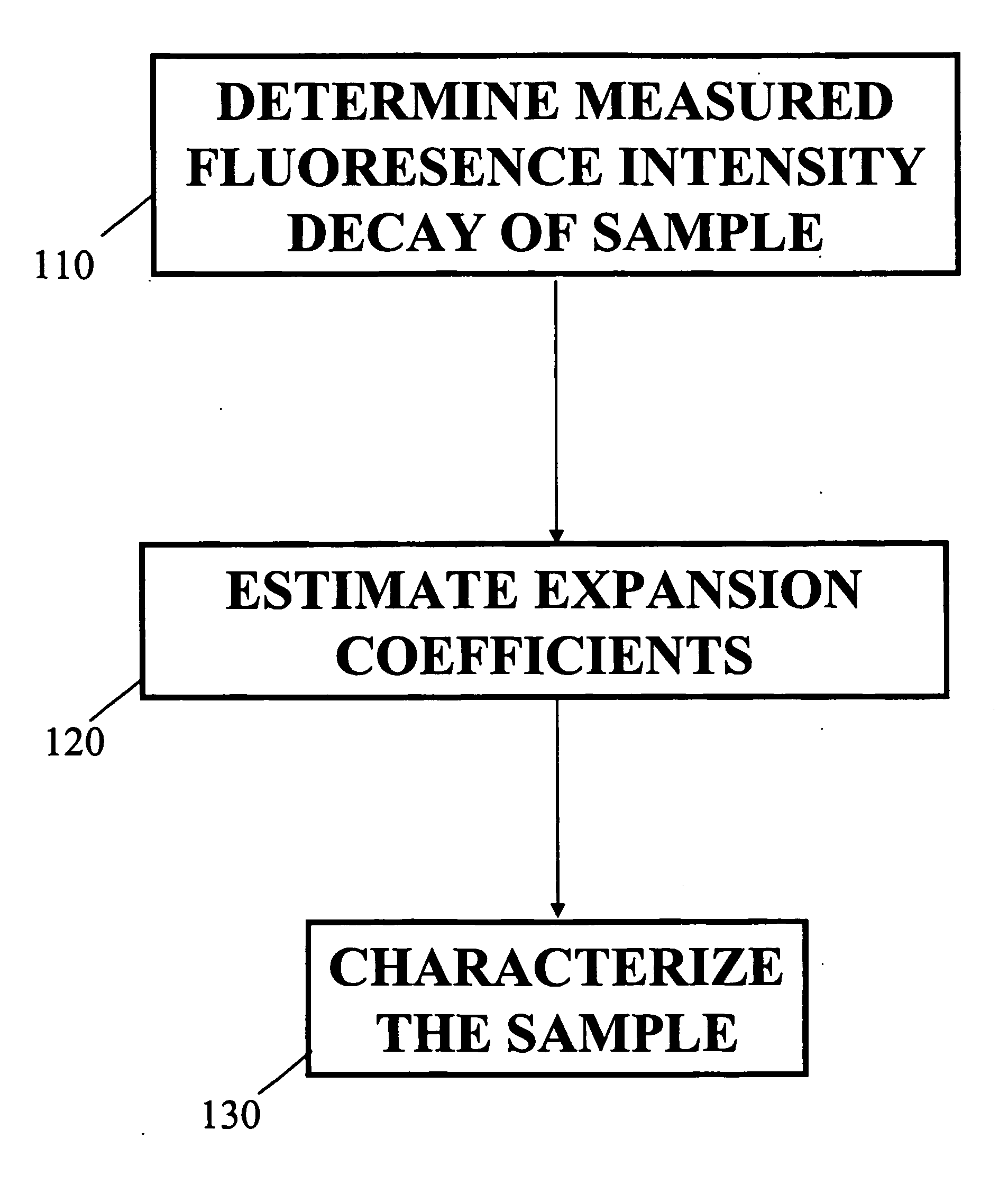
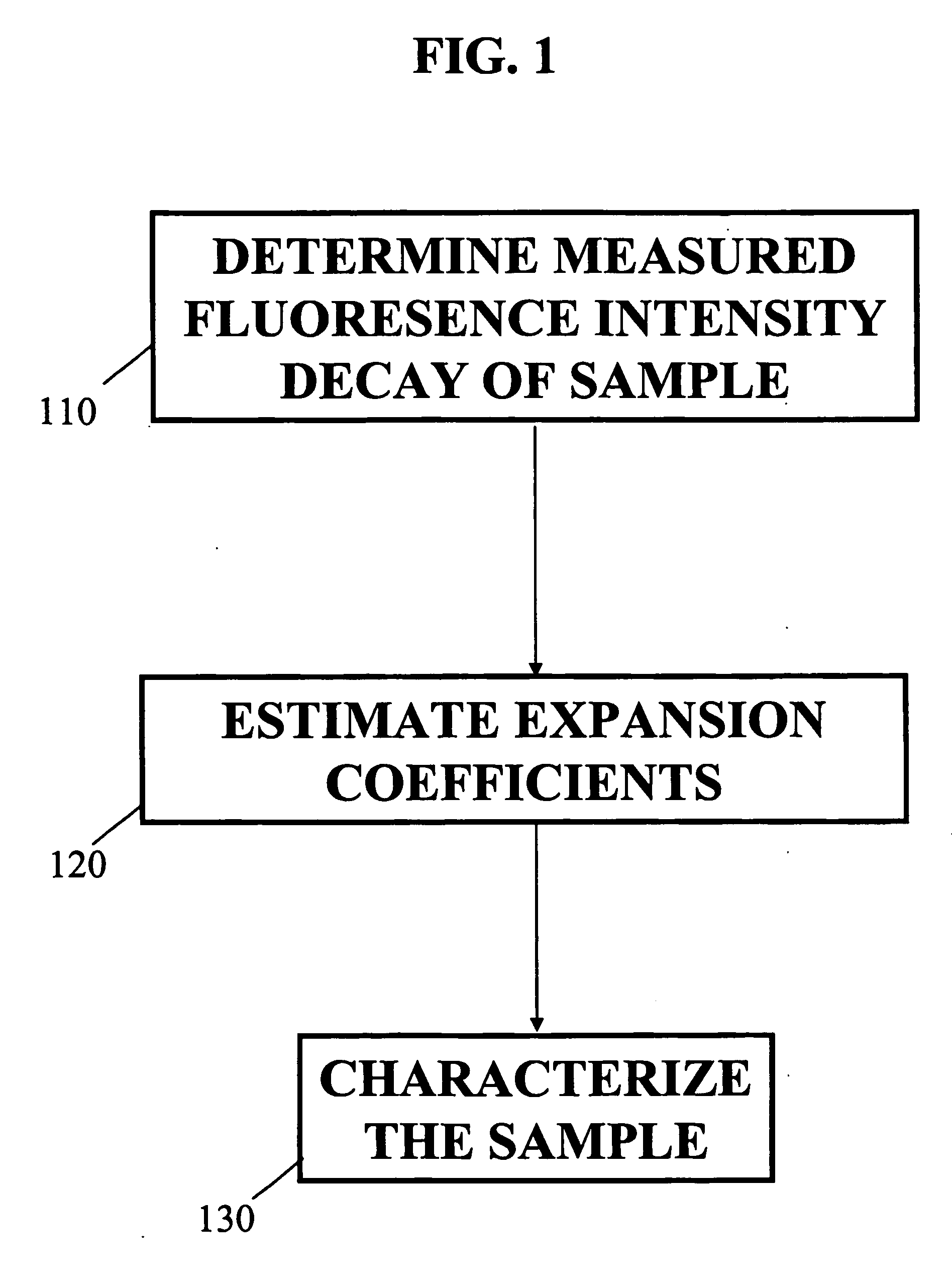
[0032]FIG. 1 illustrates a block diagram of a method for obtaining a fluorescence measurement of a sample according to an embodiment of the present invention. The sample may be excited with a short pulse of light. In Block 110 determine the measured intensity decay function of a sample. The Laguerre deconvolution technique is used to estimate the intrinsic fluorescence intensity decay of a sample. The sample may be a biological tissue, a chemical, a biochemical sample or any combination thereof, as well as any other type of sample known in the art. It should be understood that the term tissue broadly refers to any living organism that is comprised of a collection of similar cells to perform a particular function. For example the tissue may be a portion of an arterial wall, a tumorous mass or blood plasma.

[0033] The Laguerre deconvolution technique is a nonparametric method which expands the fluorescence IRF on the discrete time Laguerre basis. The Laguerre functions (LF) have been ...


PUM


Abstract

A method and system for analysis of fluorescence emission spectroscopy data and fluorescence lifetime imaging microscopy data are described. A unique Laguerre expansion can be found for fluorescence intensity decays of arbitrary form with convergence to a correct solution faster than with conventional methods. The Laguerre expansion technique includes expansion coefficients highly correlated with intrinsic fluorescence lifetimes, allowing direct characterization of fluorescence dynamics. For complex systems, conventional analysis of fluorescence intensity decay in terms of discrete exponential components can not readily provide a true representation of underlying fluorescence dynamics. Utilizing the Laguerre expansion technique, an alternative non-parametric method for analysis of time-resolved fluorescence data from various systems is described, facilitating characterization and discrimination of a sample. An ultra-fast method for analysis of fluorescence lifetime imaging is also described, facilitating real-time analysis of compositional and functional changes in samples, at a microscopic or macroscopic level.

Description

FIELD OF INVENTION [0001] Embodiments of the present invention relate to the quantitative and qualitative analysis of time resolved fluorescence emission data and fluorescence lifetime imaging microscopy data which may be used in applications in a broad range of fields including medicine, biology, biochemistry, chemistry, pharmaceutics, genetics, and others fields requiring analysis of fluorescence emission. BACKGROUND OF THE INVENTION [0002] Fluorescence spectroscopy is a nondestructive optical method extensively used to probe complex biological systems, including cells and tissues for biochemical, functional and morphological changes associated with pathological conditions. Such approaches have potential for noninvasive diagnosis in vivo. Fluorescence measurements can be categorized as either static (steady-state or time-integrated) or dynamic (time-resolved). While steady-state techniques provide an integrate spectrum over time that gives information about fluorescence emission i...

Claims


Application Information

Patent Timeline
IPC IPC(8): A61B5/05A61B6/00G01NG01N21/64
CPCA61B5/0059G01N21/6458G01N21/6408
Inventor JO, JAVIER A.MARCU, LAURAFANG, QIYINPAPAIOANNOU, THANASSIS
Owner CEDARS SINAI MEDICAL CENT
Why Eureka
Try Eureka