
Conductive Resin Composition

a technology of conductive resin and composition, which is applied in the direction of non-metal conductors, conductors, transportation and packaging, etc., can solve the problems of poor molding processability of polyphenylene ethers, deterioration of fluidity, and need for further improvement of fluidity, etc., to achieve excellent fluidity and surface luster, excellent conductivity, and low water absorption.

Inactive Publication Date: 2007-09-06
ASAHI KASEI CHEM CORP
View PDF18 Cites 17 Cited by
  • Summary
  • Abstract
  • Description
  • Claims
  • Application Information

AI Technical Summary

Benefits of technology

[0146] In the invention, besides the components described above, additive components may be added so long as they do not ruin the effects of the invention. Examples of the additive components are given below.
[0147] The additive components are known adhesion-improving agents for enhancing the affinity of an inorganic filler for a resin, flame retardants (e.g. halogenated resins, silicone flame retardants, magnesium hydroxide, aluminum hydroxide, organic phosphate compounds, ammonium polyphosphates and red phosphorus), fluorine-containing polymers having drop-preventing effect, plasticizers (e.g. oils, low-molecular weight polyolefins, poly(ethylene glycol)s and fatty acid esters), flame-retarding assistants (e.g. antimony trioxide), antistatic agents, various peroxides, antioxidants, ultraviolet absorbers, light stabilizers, and the like.
[0148] Specifically, the total amount of these components added is not more than 100 parts by mass per 100 parts by mass of the sum of the polyamide, the polyphenylene ether and the polyester.
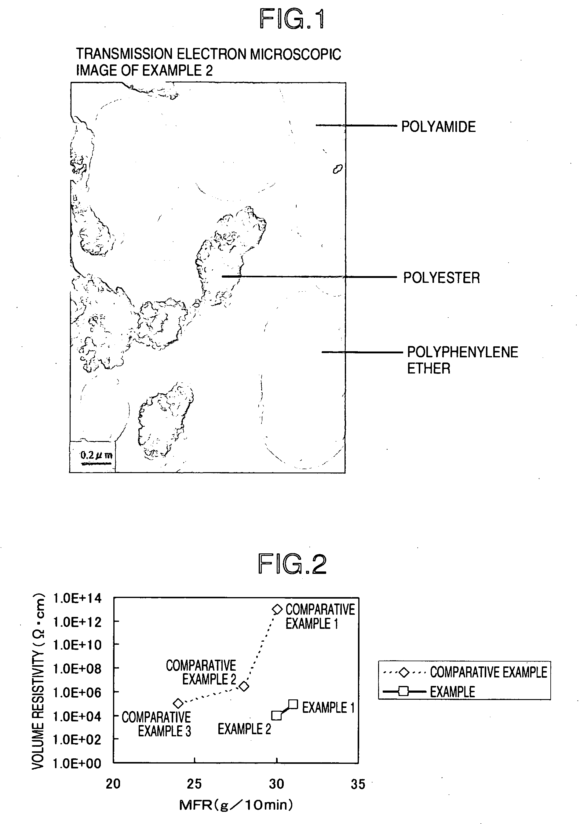
[0149] In the resin composition of the invention, it is preferable that the polyamide forms a continuous phase and that the polyphenylene ether and the polyester form a discontinuous phase. The term “discontinuous phase” used here means a phase not forming a continuous phase. The shape of the discontinuous phase may be either spherical or amorphous (rosary-shaped, string-shaped or the like). The contour of the discontinuous phase may be either smooth or uneven. These morphologies can be confirmed under, for example, a transmission microscope. A transmission microscopic image of a typical example is shown in FIG. 1. The resin composition of the invention obtains an excellent surface appearance (surface luster) owing to the formation of the discontinuous phase by the polyester though the reason is not clear.
[0150] In the invention, although the conductive carbon filler may be present in any of the phases of the polyamide, the polyphenylene ether and the polyester, the conductive carbon filler is preferably present in the polyester phase and / or the interface between the polyester phase and the polyamide phase even in a small amount. The term “interface between the polyester phase and the polyamide phase” used here means the vicinity of the boundary between the polyamide phase and the polyester phase observed under a transmission electron microscope. The resin composition of the invention is greatly improved in conductivity by the presence of even a small amount of the conductive carbon filler in the polyester phase and / or the interface between the polyester phase and the polyamide phase. The presence of the conductive carbon filler in the polyester phase and / or the interface between the polyester phase and the polyamide phase can be confirmed under a transmission electron microscope. The presence can be confirmed, for example, by cutting a piece out of a pellet or molded article of the resin composition, preparing a very thin slice from the piece by the use of an ultramicrotome, staining the surface of the slice with ruthenium chloride, osmium tetraoxide, phosphotungstic acid or the like, and observing the stained slice under a transmission electron microscope at a magnification of about 50,000.
[0151] Specific examples of processing machine for obtaining the resin composition of the invention are a single-screw extruder, twin-screw extruder, roll, kneader, Brabender Plastograph, Banbury mixer, etc. Of these, the twin-screw extruder is preferable. In particular, a twin-screw extruder with a screw diameter of 25 mm or more and a L / D ratio of 30 or more having a feed opening on the upstream side and one or more feed openings on the downstream side is preferable. As such a twin-screw extruder, a twin-screw extruder with a screw diameter of 45 mm or more and a L / D ratio of 30 or more is the most preferable.

Problems solved by technology

The polyphenylene ethers, however, are poor in molding processability by themselves.
However, in these techniques, a large amount of a conductive filler such as carbon black should be blended in order to impart conductivity sufficient to conduct electrostatic coating, so that the fluidity is deteriorated.
Moreover, further improvement of the fluidity has come to be required with an increase in the size and shape complexity of the exterior trim parts of automobiles.
Compositions obtained by conventional techniques, however, cannot easily have both a high fluidity and a high conductivity which satisfy the above requirement.

Method used


Image

  • Conductive Resin Composition
  • Conductive Resin Composition

Examples


examples

[0155] The invention is illustrated below in further detail with working examples and comparative examples but the invention is not limited by the description given in the working examples.

(Starting Materials Used)

(1) Polyamide 6,6 (hereinafter abbreviated as PA66)

[0156] Leona 1200-011, a trade name, mfd. by Asahi Kasei Chemicals Corporation

(2) Poly(ethylene terephthalate)s (hereinafter abbreviated as PET)

(2-1) NEH-2050, a trade name, mfd. by UNITICA LTD. (this polymer is hereinafter abbreviated as PET-1)

[0157] Intrinsic viscosity: IV=0.78 (measured at 20° C. and a concentration of 0.5 g / 100 ml in a solution in a phenol / tetrachloroethane (6 / 4 by mass) mixture)

(2-2) MA-1340P, a trade name, mfd. by UNITICA LTD. (this polymer is hereinafter abbreviated as PET-2)

[0158] Intrinsic viscosity: IV=0.57 (measured at 20° C. and a concentration of 0.5 g / 100 ml in a solution in a phenol / tetrachloroethane (6 / 4 by mass) mixture)

(2-3) MA-2101M, a trade name, mfd. by UNITICA LTD. (thi...

example 4

[0182] Using the same twin-screw extruder as in Example 1, PPE, a hydrogenated block copolymer and maleic anhydride were fed through the upstream-side feed opening in the proportions described in Table 1 and melt-kneaded at a preset temperature in a region from the upstream-side feed opening to a place just before the downstream-side feed opening of 320° C., a preset temperature in a region from the downstream-side feed opening to a die of 280° C., a screw speed of 300 rpm and a discharge rate of 15 kg / h, and then PA66, PET and PA / CNT-MB were fed through the downstream-side feed opening in the proportions described in Table 1 to produce resin composition pellets. The fluidity (MFR), volume resistivity, surface luster, water absorption properties and Izod impact strength of the resin composition obtained were evaluated. The values of the physical properties are described in Table 1 together with the recipe.

examples 5 to 8

[0183] Resin composition pellets were produced in the same manner as in Example 1 except for changing the recipe as described in Table 2. The fluidity (MFR), volume resistivity, surface luster, water absorption properties and Izod impact strength of the resin compositions thus obtained were evaluated. The values of the physical properties are described in Table 2 together with the changed recipes.


PUM

PropertyMeasurementUnit
diameteraaaaaaaaaa
impact strengthaaaaaaaaaa
volume resistivityaaaaaaaaaa

Abstract

Disclosed is a conductive resin composition containing a polyamide, a polyphenylene ether, a polyester and a conductive carbon filler. The resin composition has attained excellent conductivity by being added with a small amount of the conductive carbon filler, while being excellent in fluidity and surface luster. Also disclosed is a molded body formed from such a resin composition.

Description

CROSS REFERENCE TO RELATED APPLICATIONS [0001] This application claims the benefit of PCT International Application No. PCT / JP2005 / 007162 filed Apr. 13, 2005 and Japanese Application Nos. 2004-118708 and 2004-328986, filed Apr. 4, 2004 and Nov. 12, 2004 respectively in Japan, the disclosures of which are incorporated herein by reference.TECHNICAL FIELD [0002] The present invention relates to a resin composition excellent in conductivity, a master batch for a resin composition containing a polyamide and a polyphenylene ether, and a molded body formed from the resin composition. BACKGROUND ART [0003] Polyphenylene ethers are excellent not only in mechanical properties, electrical properties and heat resistance but also in dimensional stability and hence are used for various purposes. The polyphenylene ethers, however, are poor in molding processability by themselves. For improving their molding processability, a technique of blending a polyamide has been proposed and the polyphenylene...

Claims


Application Information

Patent Timeline
Patent Type & Authority Applications(United States)
IPC IPC(8): H01B1/24C08J3/22C08K3/04C08L67/00C08L71/12C08L77/00C08L77/02C08L77/06
CPCC08J3/226C08K3/04C08L67/00C08L71/12C08L77/00C08L77/02C08L77/06C08L2205/03C08L2666/14C08L2666/22C08L2666/54C08L2666/18C08K3/041
Inventor TERADA, KAZUNORIMIYOSHI, TAKAAKI
Owner ASAHI KASEI CHEM CORP
Learn More