Plasma treating apparatus and plasma treating method

a plasma treatment and plasma technology, applied in the direction of superimposed coating process, coating, electric discharge tube, etc., can solve the problems of high precision, environmental cleanness, and insufficient countermeasures, and achieve the effect of high energy irradiation

Active Publication Date: 2007-09-20
TOKYO ELECTRON LTD
View PDF42 Cites 23 Cited by
  • Summary
  • Abstract
  • Description
  • Claims
  • Application Information

AI Technical Summary

Benefits of technology

[0084] The metal oxide inclusive of Group IIIa element treated by the electron beam irradiation becomes a fused state because the temperature is raised from the surface and finally arrives at above the melting point. This fusion phenomenon is gradually penetrated into the interior of the coating by making the electron beam irradiating power large or by increasing the irradiation frequency or by making the irradiation time long, so that the depth of the irradiation fused layer can be controlled by changing such irradiation conditions. Practically, the secondary recrystallized layer suitable for achieving the object of the invention is obtained when the fusion depth is 1-50 μm.
[0085] (2) As the laser beam can be used YAG laser utilizing YAG crystal or CO2 gas laser when the medium is a gas. As the irradiation treatment of the laser beam are recommended the following conditions: Laser power:0.1-10kWLaser bean area:0.01-2500mm2Treating rate:5-1000mm/s
[0086] As previously mentioned, the layer treated by the electron beam irradiation or laser beam irradiation changes into a physically and chemically stable crystal form by transforming at a high temperature and precipitating the secondary recrystal in the cooling, so that the modification of the coating proceeds in unit of cr

Problems solved by technology

However, the technique disclosed in JP-A-H10-4083 of applying the metallic oxide of the Group IIIa element in the Periodic Table or the like indicates a relatively good resistance to plasma erosion, but it is a situation in which this technique is not a sufficient countermeasure in the field of recent semiconductor processing technique requiring a higher precision and an environmental cleanness in a severer atmosphere of the corrosive gas.
Under the plasma environment these reactions are promoted to generate a very

Method used


Image

  • Plasma treating apparatus and plasma treating method
  • Plasma treating apparatus and plasma treating method
  • Plasma treating apparatus and plasma treating method

Examples


example 1

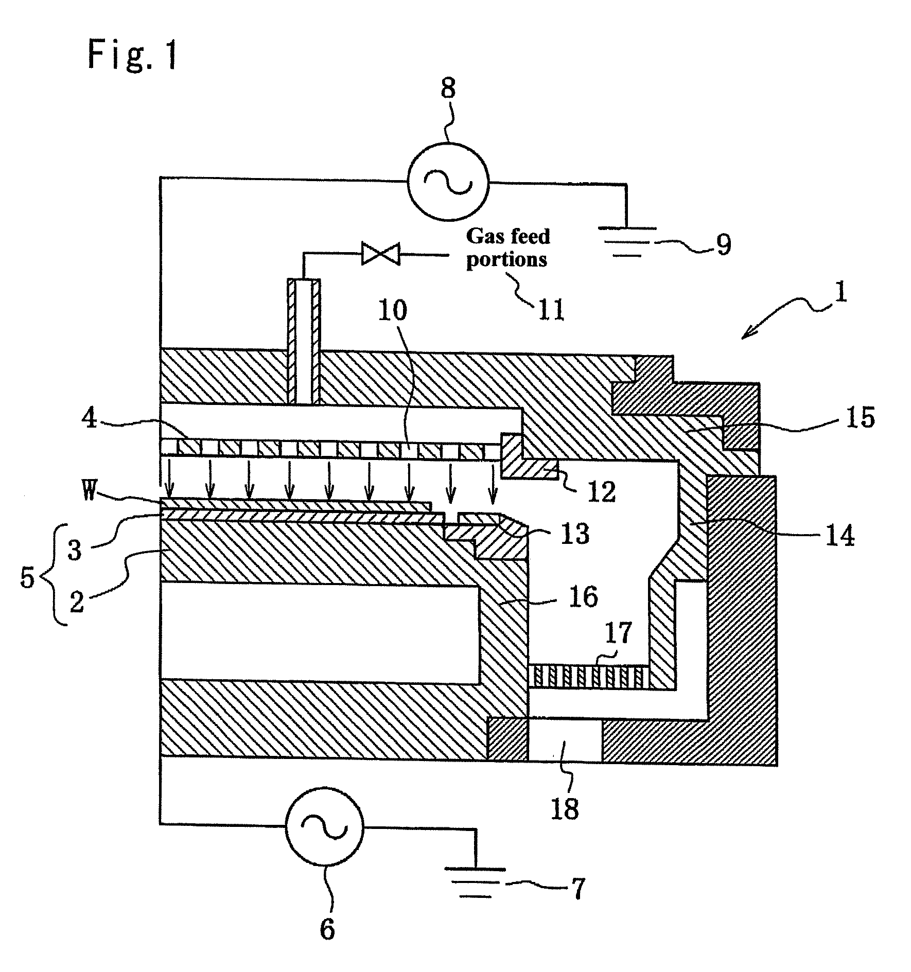
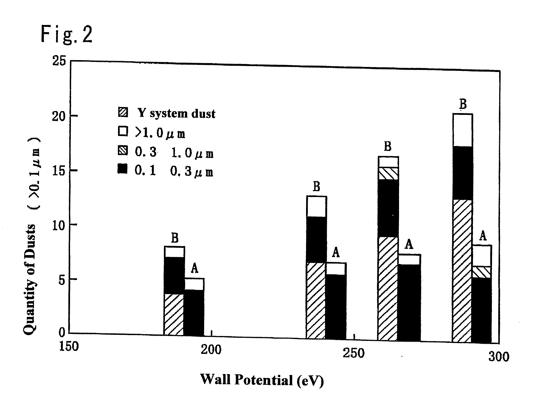
[0095] Onto a surface of an inner wall member (baffle made of aluminum) of a chamber in a plasma treating apparatus shown in FIG. 1 is sprayed Y2O3 as an example of Group IIIa metal oxide (purity: 95 mass % or more) to form a coating (Comparative Example B), while Y2O3 is sprayed to form a coating and then a surface thereof is irradiated with an electron beam to conduct secondary transformation to form a secondary recrystallized layer (Invention Example A). Into each chamber F-containing gas and CH-containing gas are alternately and repeatedly introduced to conduct a plasma treatment, whereby the Y2O3 spray coating is weakened, and a difference between potential of chamber wall and plasma potential is changed to 200-300 V by controlling a quantity of high frequency power applied to a mount base for a semiconductor wafer as a body to be treated through plasma to measure a quantity of dust (particles) generated on the semiconductor wafer at each potential difference. The results are s...

example 2

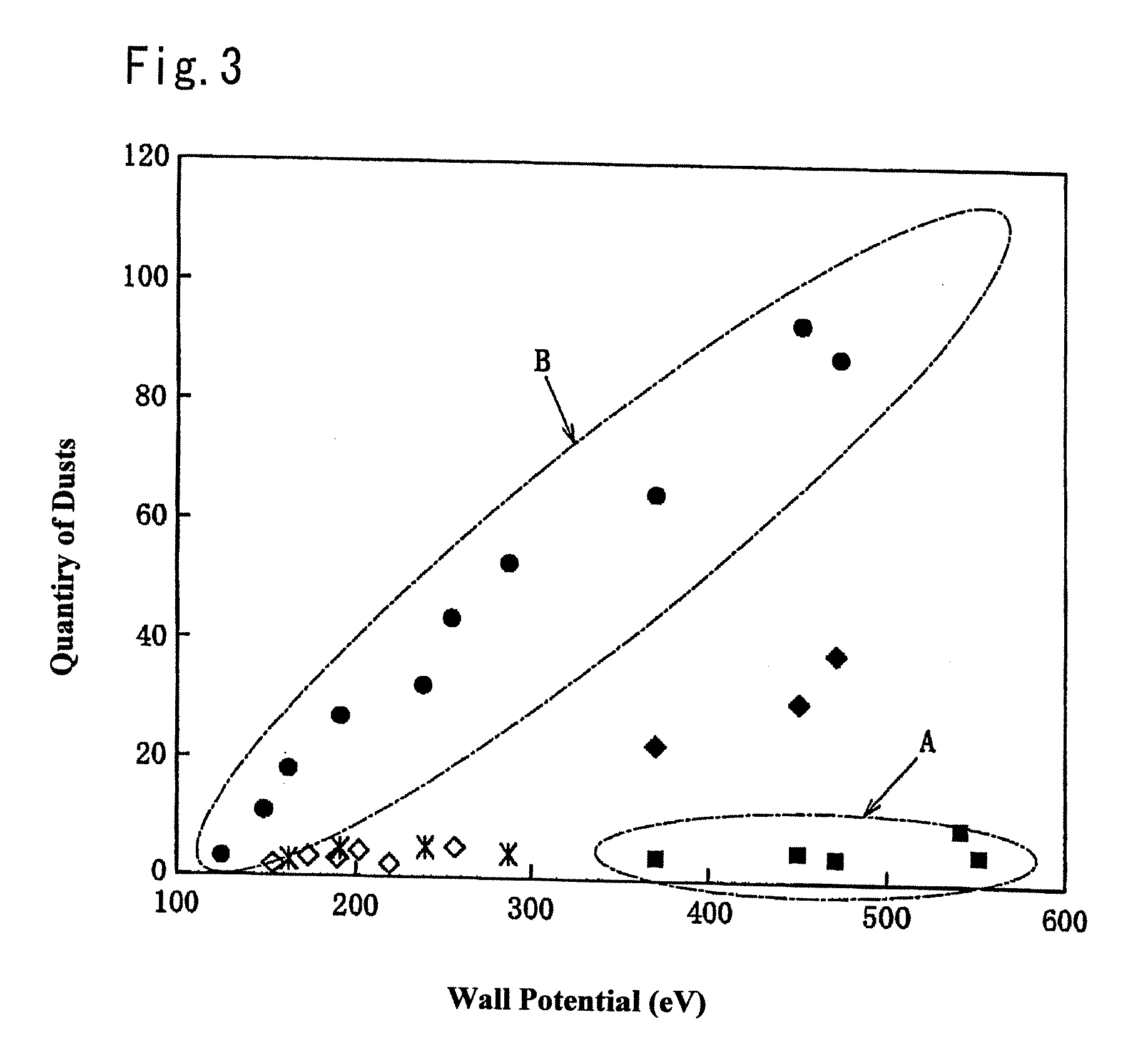
[0097] In order to examine a limit value of potential difference (range capable of suppressing the occurrence of dust resulted from the coating (yttrium)) between inner wall members in the plasma treating container (lower aluminum insulator, baffle, deposhield) and plasma, the coating formed by spraying Y2O3 onto the surface of the inner wall member (Comparative Example B) and the coating formed by spraying Y2O3 onto a surface thereof and by irradiating with an electron beam to conduct secondary transformation to form a secondary recrystallized layer (Invention Example A) are provided like Example 1. F-containing gas and CH-containing gas are alternately and repeatedly introduced into each treating vessel to conduct a plasma treatment, whereby the Y2O3 spray coating is weakened, and a potential difference between the member or the like and plasma is changed by controlling a quantity of high frequency power applied to a lower electrode to measure a quantity of dust (particles) genera...


PUM

PropertyMeasurementUnit
Electric potential / voltageaaaaaaaaaa
Poweraaaaaaaaaa

Abstract

There are proposed a plasma treating apparatus and a plasma treating method using the same capable of improving the durability of site, member and parts in a chamber used for plasma etching in a corrosive gas atmosphere, which are exposed to the plasma atmosphere, and improving the resistance to plasma erosion of a coating formed on the surface of the member or the like in the corrosive gas atmosphere and preventing the occurrence of particles of a corrosion product even under a high plasma power. As a means therefore, in a plasma treating apparatus wherein a surface of a body to be treated in a chamber is subjected to a plasma treatment with an etching gas, at least surfaces of sites of the chamber itself exposing to the plasma atmosphere, or surfaces of a member or parts accommodated in the chamber are covered with a composite layer including a porous layer made from a metal oxide and a secondary recrystallized layer of the metal oxide formed on the porous layer.

Description

FIELD OF THE INVENTION [0001] This invention relates to a plasma treating apparatus and a plasma treating method used in the field of the semiconductor processing technique. Particularly, the invention relates to a plasma treating apparatus and a plasma treating method for subjecting a semiconductor element or the like to a plasma etching under an environment constituted with an atmosphere of a halogen gas, an inert gas, oxygen, hydrogen or the like, or an atmosphere of a gas containing fluorine and a fluorine compound (hereinafter referred to as “F-containing gas”) and a hydrocarbon gas (hereinafter referred to as “CH-containing gas”), or an environment of alternately and repeatedly forming these atmospheres. BACKGROUND OF THE INVENTION [0002] In case of treating the device used in the field of semiconductor and liquid crystal, there is frequently utilized plasma energy of a halogen based corrosive gas having a high corrosiveness. For example, in a plasma etching treatment (process...

Claims


Application Information

Patent Timeline
IPC IPC(8): C23F1/00H01L21/306
CPCH01J37/32477C23C28/042H01L21/3065H01J37/32082H01J37/32091H01J37/32495
Inventor KOBAYASHI, YOSHIYUKI
Owner TOKYO ELECTRON LTD
Why Eureka
Try Eureka