[0020] One or more of the foregoing problems or limitations are addressed in accordance with one aspect of the present invention, by a treatment or deionization
system for alimentary or similar fluids, such as a whey or
plant syrup
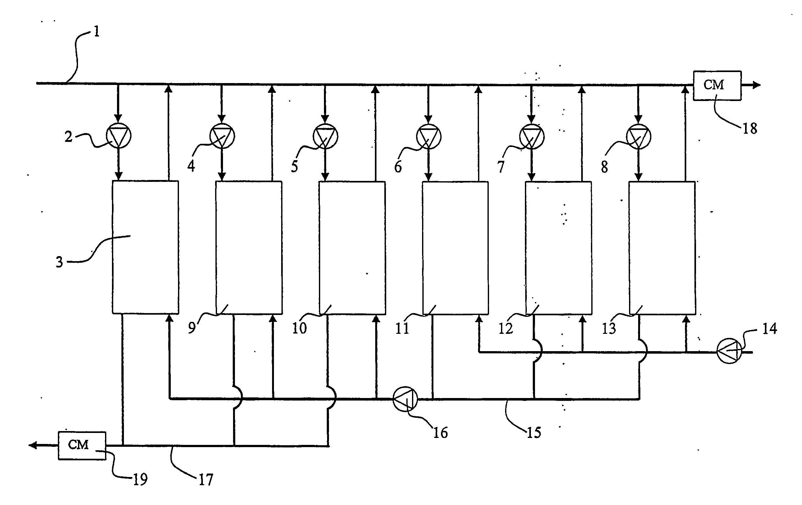
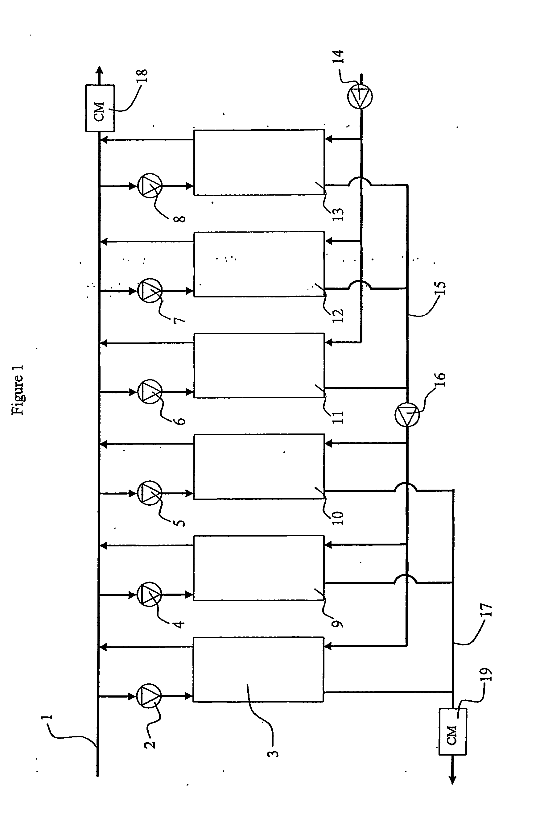
demineralization system, wherein an arrangement of plural electrically operated membrane separation units, including electrodialysis (ED), reversing electrodialysis (EDR), filled cell electrodialysis (EDI), and / or filled cell reversing electrodialysis (EDIR) units operate to demineralize a feed
stream and to transfer minerals or other components of the feed into one or more concentrate streams. The
processing units, each having one or more inlets and outlets, are arranged in groupings of one or more units in an order corresponding generally to the direction of the bulk movement of the feed fluid which is to be treated, and the groups form process-related stages with two or more stages in a treatment line configured such that the concentrate stream or streams proceed from
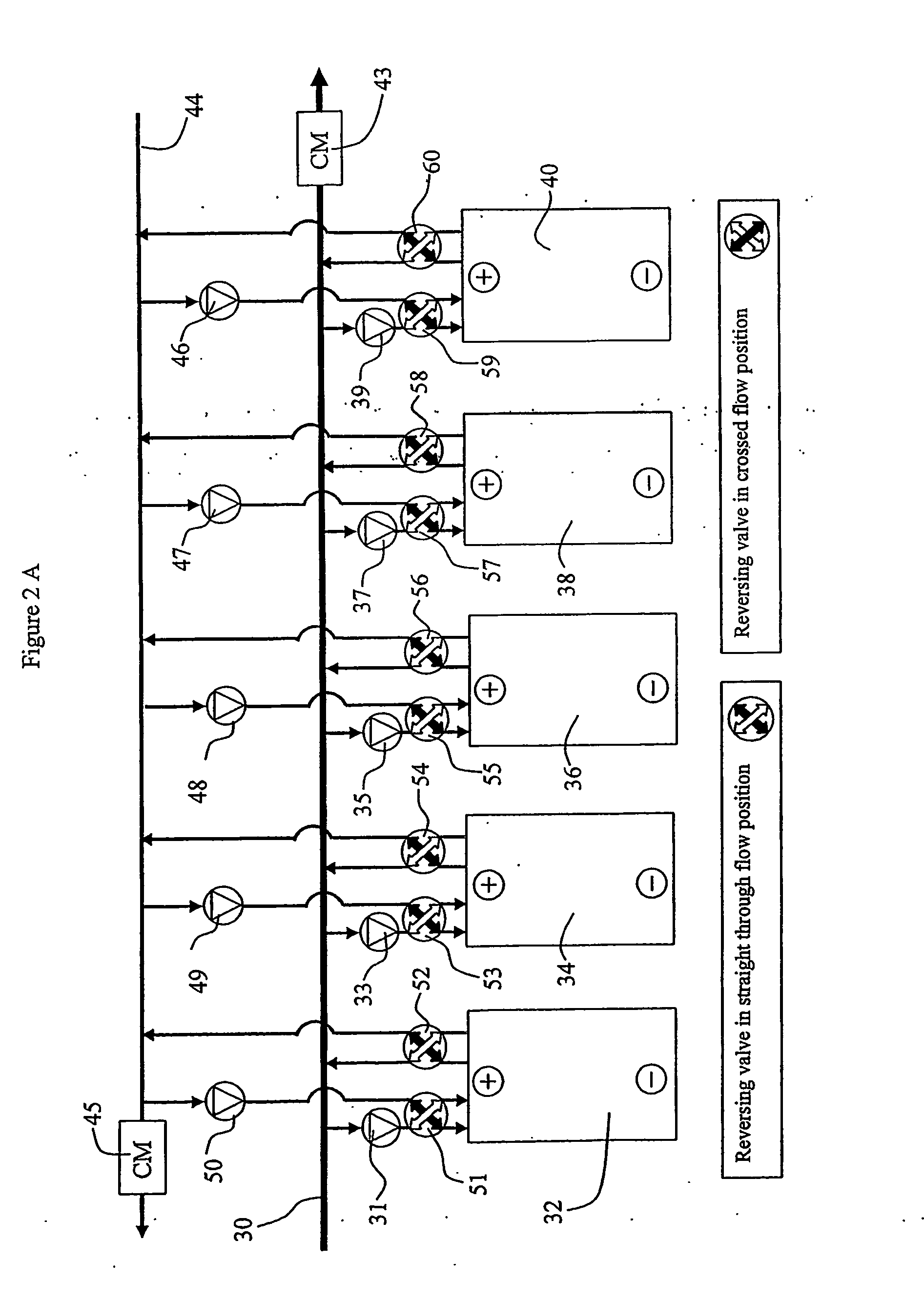
one stage to the next in a sense or order substantially opposite to that of the feed / product stream. Thus, as the feed is becoming demineralized, it passes progressively to units utilizing the earlier, less mineralized portions of the concentrate stream. With this architecture, advantageously, as the feed is treated its
conductivity may drop, while as the concentrate acquires impurities from the feed its
conductivity may rise, so that the mineral burden and the electrical
conductivity of the feed and concentrate streams are more closely “matched” as the streams pass through each unit along the treatment line. Arranging the
two fluid flows in opposite sense results in an improved match of electrical conductivity of the feed and concentrate in a processing unit, which reduces the incidence of extreme
voltage disparities in the electrodialysis cells, and may also result in a closer match of the mineral burdens that reduces concentration gradients across the membranes of the processing units and thus lowers back-
diffusion of certain components.
Conductivity matching avoids such
adverse conditions as polarization and excessive
water splitting, so that control of the fluid treatment to desired set points at each stage is more readily achieved, and a common cause of scaling or
fouling is eliminated.
[0021] In a treatment line having plural stages arranged in accordance with the present invention, different stages may be run with different electrical operating parameters. Alternatively, or in addition, different stages may employ different types of ED units. One
system may include, e.g., unfilled ED units in
one stage and EDI units in a later stage. Another embodiment of a system may be implemented entirely with (unfilled) ED treatment units, but with
one stage having membranes that offer distinctly different permeability characteristics or selectivity than another stage. Operation of the system for a particular feed liquid is set by adjusting the operation of different units—for example, setting the volts per
cell pair in each electrical stage—to tailor the ion removal and current efficiency in accordance with the type of unit and the fluid quality / composition prevailing in that stage, or the load or conductivity along the process line. This is done to enhance overall operation, e.g., increase
process efficiency or
throughput, while avoiding problems that often arise during treatment. For example, one may operate substantially everywhere below polarization, and may control to a
high current level in one or more early stages along the feed conduit, yet suffer little
power loss through the flow manifolds. Moreover, the different stages may operate with different but changing control regimens. For example, a first ED stage may be controlled to present a certain quality of partially-treated feed at the transition between the ED stage and an EDI stage, such that each stage avoids
protein fouling, denaturing or
charring, or complications that would otherwise arise in a
biological fluid electrodeionization system. The process line may also be controlled to optimize
throughput in other ways, for example to maximize the amount of fluid treated consistent with achieving a
target level of product quality, or to enhance the removal or
recovery of a specific component by altering
treatment parameters in one stage that primarily affects the quality, separation or
recovery of that specific component.

