Material for organic electroluminescence device and organic electroluminescence device using the same

a technology of electroluminescence device and material, which is applied in the direction of thermoelectric device, discharge tube luminescnet screen, natural mineral layered product, etc., can solve the problems of compound and difficult application to phosphorus luminescent device, and achieve superior heat resistance, prolong the life, and enhance the current efficiency of light emission

Inactive Publication Date: 2007-09-27
IDEMITSU KOSAN CO LTD
View PDF1 Cites 221 Cited by
  • Summary
  • Abstract
  • Description
  • Claims
  • Application Information

AI Technical Summary

Benefits of technology

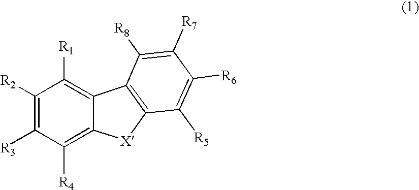
[0034]each of R2 and R7 is not an amino group.
[0043]Employing the compound represented by the general formula (1) of the present invention as the material for an organic electroluminescence device provides the organic electroluminescence device with an enhanced current efficiency of light emission, without any pixel defects, with superiority in heat resistance and with prolonged lifetime.
[0044]Therefore, the organic EL device of the present invention is very useful for applications such as light sources of various electronic instruments.
[0045]The present invention provides a material for an organic electroluminescence device comprising a compound represented by a following general formula (1):
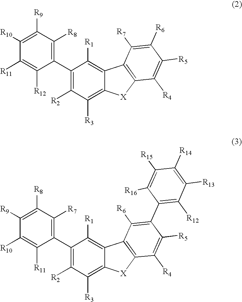
[0048]The present invention provides a material for an organic electroluminescence device which comprises a compound represented by a following general formula (2) or a following general formula (3):
[0049]R1 to R16 in the general formulae (2) and (3) each independently represents a hydrogen atom, a halogen atom, an alkyl group having 1 to 40 carbon atoms and further may have a substituent, a heterocyclic group having 3 to 20 carbon atoms and further may have a substituent, an alkoxy group having 1 to 40 carbon atoms and further may have a substituent, a non-condensed aryl group having 6 to 40 carbon atoms and further may have a substituent, a condensed aryl group having 6 to 12 carbon atoms and further may have a substituent, a mixed aryl group of a condensed aryl group and a non-condensed aryl group while the mixed aryl group has 12 to 40 carbon atoms and further may have a substituent, an aryloxy group having 6 to 20 carbon atoms and further may have a substituent, an aralkyl group having 7 to 20 carbon atoms and further may have a substituent, an alkenyl group having 2 to 40 carbon atoms and further may have a substituent, an alkylamino group having 1 to 40 carbon atoms and further may have a substituent, an aralkylamino group having 7 to 60 carbon atoms and further may have a substituent, an alkylsilyl group having 3 to 20 carbon atoms and further may have a substituent, an arylsilyl group having 8 to 40 carbon atoms and further may have a substituent, an aralkylsilyl group having 8 to 40 carbon atoms and further may have a substituent, an alkylgermanium group having 3 to 20 carbon atoms and further may have a substituent, an arylgermanium group having 8 to 40 carbon atoms and further may have a substituent, an aralkylgermanium group having 8 to 40 carbon atoms and further may have a substituent, a keto aryl group having 7 to 40 carbon atoms and further may have a substituent, an alkylhalide group having 1 to 40 carbon atoms and further may have a substituent, or a cyano group.

Problems solved by technology

However, Patent Literature 4 fails to clarify a superiority in device performance over other carbazolyl skeletons and further, it does not describe about a substituent at 2, 8-positions of dibenzofuran or of dibenzothiophene.
However, the compound seems to be difficult in applying to a phosphorus luminescent device because it has the anthracene skeleton with a narrow triplet energy gap.
Moreover, although Patent Literature 7 below indicates benzofuran compound bonded to pyrene skeleton, the compound also seems to be difficult in applying to the phosphorus luminescent device because the pyrene skeleton has also a narrow triplet energy gap, and further, Patent Literature 7 fails to describe any example about the compound.

Method used


Image

  • Material for organic electroluminescence device and organic electroluminescence device using the same
  • Material for organic electroluminescence device and organic electroluminescence device using the same
  • Material for organic electroluminescence device and organic electroluminescence device using the same

Examples


synthesis example 1

[0150]The route for synthesis of Compound (B-1) is shown in the following.

[0151]Under the atmosphere of argon gas, 2,8-dibromodibenzothiophene in an amount of 1.31 g (3.83 mmol), boronic acid A in an amount of 2.50 g (9.12 mmol) and tetrakis(triphenylphosphine)palladium in an amount of 0.527 g (0.456 mmol) were placed into a three neck flask with a capacity of 300 milliliter, and the air inside the flask was replaced with argon gas. Adding 1,2-dimethoxyethane in an amount of 27.4 milliliter and 2.0 M sodium carbonate aqueous solution in an amount of 13.7 milliliter (27.4 mmol) into the flask, the resultant solution was refluxed by heating for 9 hours under the atmosphere of argon gas. Water in an amount of 100 milliliter and methylene chloride in an amount of 100 milliliter were added to the resultant reaction solution, and an organic layer was separated, followed by drying with the use of anhydride magnesium sulfide. After concentrating the dried mixture under reduced pressure by m...

synthesis example 2

[0153]The route for synthesis of Compound (A-1) is shown in the following.

[0154]Under the atmosphere of argon gas, 2,8-dibromodibenzofuran in an amount of 2.53 g (7.76 mmol), boronic acid A in an amount of 5.07 g (18.5 mmol) and tetrakis(triphenylphosphine)palladium in an amount of 1.07 g (0.925 mmol) were placed into a three neck flask with a capacity of 300 milliliter, and the air inside the flask was replaced with argon gas. Adding 1,2-dimethoxyethane in an amount of 55.5 milliliter and 2.0 M sodium carbonate aqueous solution in an amount of 27.8 milliliter (55.5 mmol) into the flask, the resultant solution was refluxed by heating for 9 hours under the atmosphere of argon gas. Water in an amount of 100 milliliter and methylene chloride in an amount of 100 milliliter were added to the resultant reaction solution, and an organic layer was separated, followed by drying with the use of anhydride magnesium sulfide. After concentrating the dried mixture under reduced pressure by means ...

synthesis example 3

[0156]The route for synthesis of Compound (B-16) is shown in the following.

[0157]Under the atmosphere of argon gas, 2,8-dibromodibenzothiophene in an amount of 2.15 g (6.29 mmol), boronic acid B in an amount of 2.97 g (15.0 mmol) and tetrakis(triphenylphosphine)palladium in an amount of 0.867 g (0.750 mmol) were placed into a three neck flask with a capacity of 300 milliliter, and the air inside the flask was replaced with argon gas. Adding 1,2-dimethoxyethane in an amount of 45.0 milliliter and 2.0 M sodium carbonate aqueous solution in an amount of 22.5 milliliter (45.0 mmol) into the flask, the resultant solution was refluxed by heating for 10 hours under the atmosphere of argon gas. Water in an amount of 100 milliliter and methylene chloride in an amount of 100 milliliter were added to the resultant reaction solution, and an organic layer was separated, followed by drying with the use of anhydride magnesium sulfide. After concentrating the dried mixture under reduced pressure by...


PUM

PropertyMeasurementUnit
light emitting wavelengthaaaaaaaaaa
work functionaaaaaaaaaa
thicknessaaaaaaaaaa

Abstract

A material for organic electroluminescence device with specific structure. An an organic electroluminescence device comprising a cathode, an anode and an organic thin film layer which is sandwiched between the cathode and the anode and comprises at least one layer, wherein at least one layer in the organic thin film layer contains a material for the organic electroluminescence device described above. An organic electroluminescence device with excellent efficiency of light emission, without pixel defects, which is superior in heat resistance and prolonged lifetime is obtained.

Description

TECHNICAL FIELD[0001]The present invention relates to a material for an organic electroluminescence device and an organic electroluminescence device employing the same. Particularly, the present invention relates to the material for the organic electroluminescence device with an enhanced efficiency of light emission, free from defects in pixels, superior in heat resistance and with prolonged lifetime, together with the organic electroluminescence device employing the material.BACKGROUND ART[0002]An organic electroluminescence (“electroluminescence” will be occasionally referred to as “EL”, hereinafter) device is a spontaneous light emitting device which utilizes the principle that a fluorescent substance emits light by energy of recombination of holes injected from an anode and electrons injected from a cathode when an electric field is applied. Since an organic EL device of the laminate type driven under a low electric voltage was reported by C. W. Tang et al. of Eastman Kodak Comp...

Claims


Application Information

Patent Timeline
Patent Type & Authority Applications(United States)
IPC IPC(8): H01L51/54C09K11/06
CPCC09K11/06H05B33/20C09K2211/1029C09K2211/1044C09K2211/1059C09K2211/1088C09K2211/1092C09K2211/1096C09K2211/185C09K2211/186H01L51/0061H01L51/0067H01L51/0072H01L51/0073H01L51/0074H01L51/0081H01L51/0094H01L51/5016H01L51/5048H05B33/14C09K2211/1014C07D307/91C07D333/76C07D409/14C09K2211/1007H10K85/631H10K85/636H10K85/654H10K85/6576H10K85/6574H10K85/324H10K85/40H10K85/6572H10K50/14H10K50/11H10K2101/10
Inventor NAKANO, YUKIIWAKUMA, TOSHIHIROMATSUURA, MASAHIDEIKEDA, HIDETSUGU
Owner IDEMITSU KOSAN CO LTD
Why Eureka
Try Eureka