
Fiberoptic laser Doppler probe

a fiberoptic laser and probe technology, applied in the field of fiberoptic laser doppler probes, can solve the problems of large soft tissue defects, post-operative facial weakness or deafness, and inability to record hearing and facial function during surgery, so as to prevent any light distortion and accurately measure the viability of the flap

Inactive Publication Date: 2008-01-17
DAVID KAYLIE
View PDF7 Cites 3 Cited by
  • Summary
  • Abstract
  • Description
  • Claims
  • Application Information

AI Technical Summary

Benefits of technology

[0009] According to the present invention, the laser Doppler technique generally measures blood flow in the very small blood vessels of the microvasculature, such as the low-speed flows associated with nutritional blood flow in capillaries close to the skin surface and the flow in the underlying arterioles and venules involved in regulation of skin temperature. Generally, the tissue thickness sampled is approximately 1 mm, the capillary diameter is approximately 10 microns and the velocity spectrum measurement approximately 0.01 to 10 mm / s. In general, single point measurements give a high temporal resolution (40 Hz data rates are typical) enabling rapid blood flow changes to be recorded, and laser Doppler techniques can provide spatial information and have the ability to average blood flow measurements over large areas. Fiber-optic systems can measure at tissue sites not easily accessible to a laser beam. For example measurements in the brain tissue, mouth, gut, colon, muscle and bone.
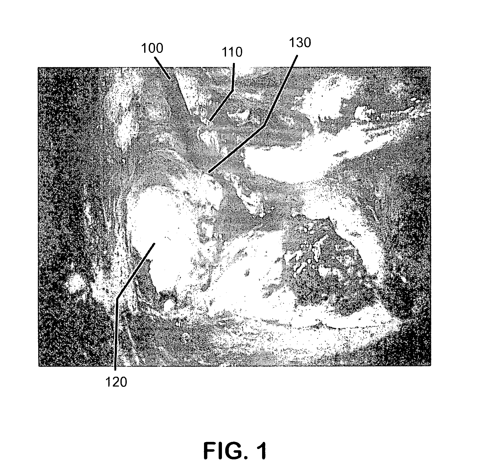
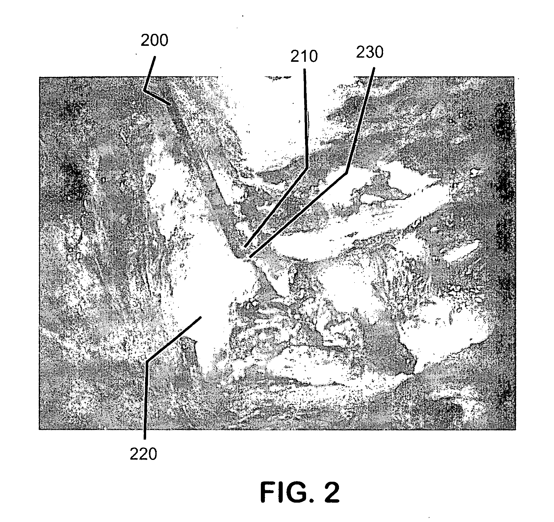
[0012] In accordance with an embodiment of the present invention, a uniquely designed probe is provided which allows the use of standard LDF measurement systems. The unique probe of the invention enables the utilization of the angle at which the facial nerve enters the boney canal under the anatomic region called the transverse crest to access the necessary tissue. The crux of the invention resides in a LDF probe, the tissue-contacting tip of which is angled. The incorporation of the correct angle in the probe tip enables the probe to be securely fixed to the nerve surface under study. The angled probe can also be placed on the cochlea during middle fossa approaches for acoustic neuroma tumor removal. The angle is necessary to allow adequate probe contact with the convex cochlea surface. The modified probe may be held in place with a standard instrument holder. This allows accurate readings of perfusion rates.
[0013] Generally, it is helpful to use a drop of saline solution on the end of the modified probe before securing it to the surface of the nerve. This helps to complete the sealing of the angled fiber end and the surface of the nerve tissue, given that there may not be an exact fit. For example, the saline may serve to seal any air gaps and prevent any light distortion.
[0014] Stretching or compression of the nerve or artery during surgery can affect blood flow. Knowing the effect on perfusion will allow a surgeon to take preemptive measures. In addition, knowing the microcirculation status of a free flap after it has been inset into the defect will allow for an accurate measurement of flap viability.
[0026] (B) Neurosurgical Aneurysm Surgery—The LDF probe may be placed on intracranial aneurysms to assess blood flow in collateral vessels prior to clipping of the aneurysm. In general, this will increase intra-operative safety and allow for a quantifiable assessment of patency of feeding vessels; and

Problems solved by technology

Most importantly, this artery is the sole blood supply to the inner ear, and disruption of this artery causes deafness.
Dissection of the tumor may cause disruption of this artery causing post-operative facial weakness or deafness in patients who had useful hearing pre-operatively.
Unfortunately, promontory recordings of hearing and facial function are not possible during surgery.
These surgeries can leave large soft-tissue defects that can seriously impair function and it is imperative to reconstruct these cancer defects.
If that happens, the flap will not survive and the patient will need to undergo an additional reconstructive surgery.
Theses are non-quantifiable methods.

Method used


Image

  • Fiberoptic laser Doppler probe
  • Fiberoptic laser Doppler probe
  • Fiberoptic laser Doppler probe

Examples


Embodiment Construction

In accordance with an embodiment of the present invention, a

[0033] Laser Doppler Fiber-optic (LDF) probe is provided to measure microvascular blood flow in tissue during surgery to obtain a measure of real-time tissue perfusion.

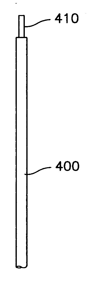
[0034] As tissue structures may comprise small, non-planar surfaces (for example, the facial nerve is approximately 1 mm in diameter), in general, a very small, flexible probe is needed to get a good reading from the tissue. In accordance with an embodiment of the present invention the probe includes a specially designed LDF probe that has a fiber-optic cable with an angled, polished tip. This generally allows for maximal contact with the tissue surface during surgery. The fiber-optic cable may be placed through a malleable tube that may be held in place using a standard surgical retractor holder.

[0035] Unlike standard LDF probes, an embodiment of the present invention calls for the fiberoptic cable to have an angled tip and for placing the cable through a ...


PUM


Abstract

A laser Doppler flowmetry probe and method for monitoring blood flow in a locus of a tissue medium proximately located at the distal end, the probe having a proximal and distal end and comprising: an optical conductor, having one end located at the distal end, an opposite end located at the proximal end and having a central axis, that guides radiation to said distal end and guides radiation scattered from the tissue medium to the proximal end for providing an indicative of the blood flow in the locus of the tissue medium; and wherein the distal end of the optical conductor is angled with respect to the central axis of the optical conductor so as to provide maximal contact with the tissue.

Description

FIELD OF THE INVENTION [0001] The present invention relates to a method and apparatus for recording microvascular blood flow in tissue during surgery, giving a measure of real-time tissue perfusion. BACKGROUND OF THE INVENTION [0002] The invention is based on the use of laser-Doppler technique (LDF) for measuring the superficial circulation of blood in tissue. This technique is described, for instance, in U.S. Pat. Nos. 3,511,227, 4,109,647, SE 419 678 and the articles “In Vivo Evaluation of Microcirculation by Coherent Light Scattering”, Stern, N. D., Nature, Vol. 254, pp. 56-58, 1975; “A New Instrument for Continuous Measurement of Tissue Blood Flow by Light Beating Spectroscopy”, Nilsson, G. E., Tenland, T. and Oberg, P. A., IEE trans., BME-27, pp. 12-19, 1980, and “Evaluation of a Laser Doppler Flow Meter for Measurement of Tissue Blood Flow”, Nilsson, G. E., Tenland, T. and Oberg, P. A., IEE trans., BME-27, pp. 597-604, 1980. [0003] In principle, this technique involves directi...

Claims


Application Information

Patent Timeline
IPC IPC(8): A61B5/0265A61B18/22
CPCA61B5/0261
Inventor DAVID, KAYLIE
Owner DAVID KAYLIE
Learn More