Light energy conversion material

a technology of light energy and material, applied in the field of light energy conversion material, can solve the problems of insufficient amount of electron donor introduced in the pore, insufficient chemical energy conversion reaction, and inability to achieve the effect of increasing and improving the efficiency of light energy conversion

Inactive Publication Date: 2008-03-06
TOYOTA CENT RES & DEV LAB INC
View PDF6 Cites 7 Cited by
  • Summary
  • Abstract
  • Description
  • Claims
  • Application Information

AI Technical Summary

Benefits of technology

[0017]For these reasons, the porous material including the electron donor in the skeleton is used in the present invention. Accordingly, many of the electron donors are exposed to the surface of the pore of the porous material. When the electron acceptors are disposed on the surface of the porous material, the state where the pair of the electron donor and the electron acceptor is disposed in a high density is formed. Therefore, when the light energy is absorbed, the occurrence of electrons and holes by the charge separation is accelerated. As a result, the electron transfer efficiency is improved, and thereby the light energy conversion efficiency is significantly improved. The porous material including the electron donor in the skeleton has a high light-energy-absorption efficiency because the electron donors are present in the skeleton in a high density. Moreover, the energy excited by the absorption of the light energy can be transferred in the skeleton of the porous material, and thereby the electron transfer efficiency to the electron acceptor is improved. Furthermore, such a transfer efficiency of the excited energy in the skeleton depends on the structure of the porous material. Therefore, the use of the porous material having a more regularly arranged structure allows the light energy conversion efficiency to be improved. Still furthermore, the physical stabilities of the electron donor and the electron acceptor are improved by fixing the electron acceptor in the narrow space such as the pore and the skeleton of the porous material including the electron donor in the skeleton. As a result, the durability of the light conversion material is improved.
[0018]The present invention makes it possible to provide a light energy conversion material which can advance a light energy conversion reaction with a high efficiency, resulting in the significant improvement in the light energy conversion efficiency, and, further, which can improve the physical stabilities of an electron donor and an electron acceptor to give the light conversion material a sufficient durability.

Problems solved by technology

On the other hand, since the photoactive pigment and the electron acceptor were also disposed in the pore space, it is spatially difficult to introduce a sufficiently large amount of the electron donor in the pore.
Consequently, the introduced amount of the electron donor is not always sufficient.
Even if the pore space is filled with the sufficient amount of the photoactive substance and the electronic substance in the light energy conversion material, a chemical energy conversion reaction is not always sufficiently advanced using the pore space as a reaction field.
Thus the energy conversion efficiency is not always sufficient.

Method used


Image

  • Light energy conversion material
  • Light energy conversion material
  • Light energy conversion material

Examples


synthesis example 1

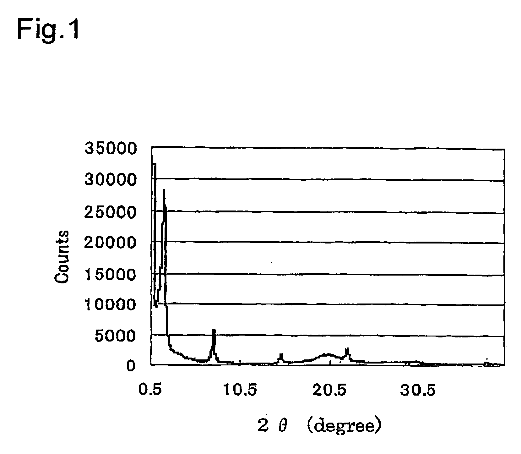
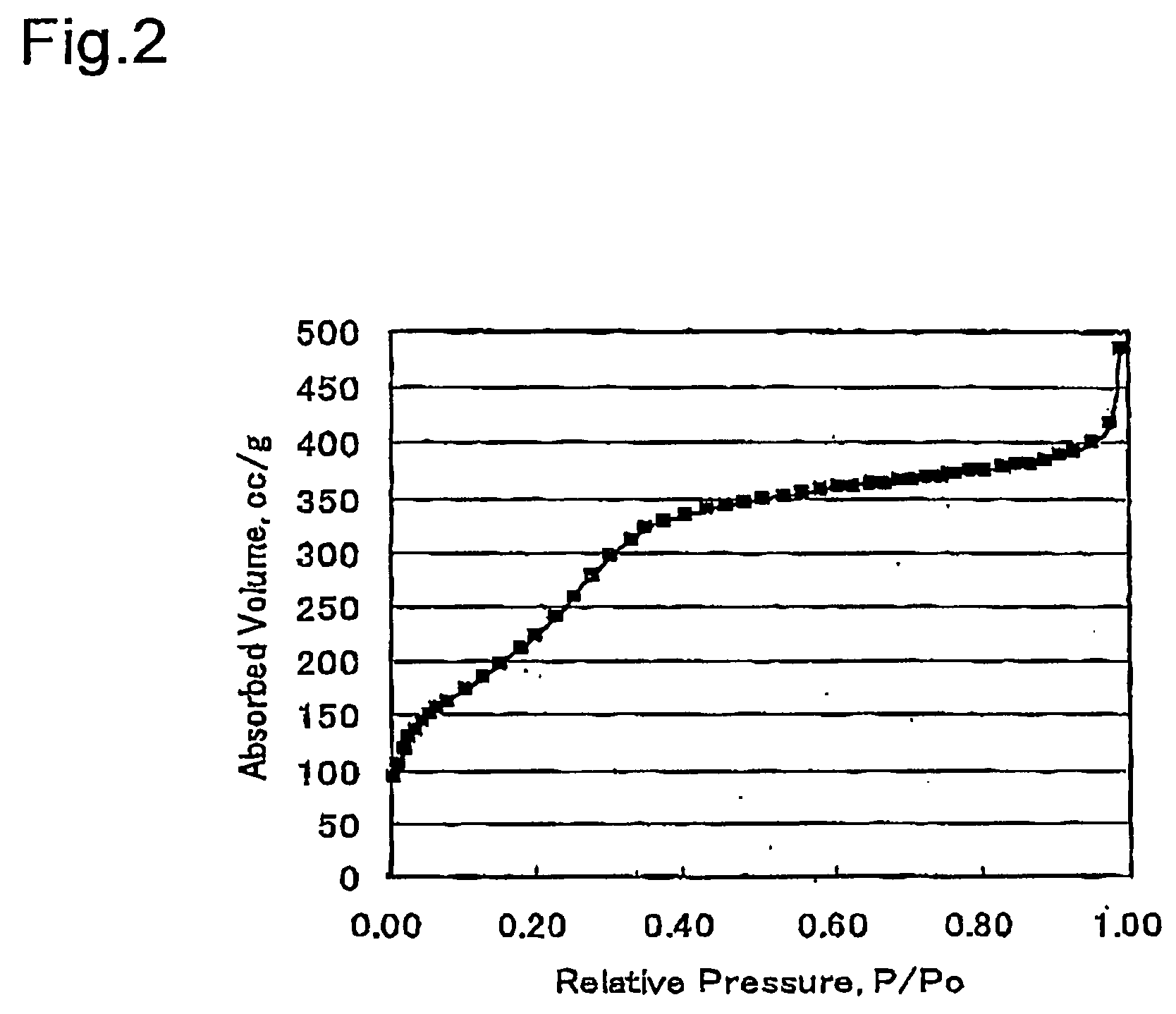
Synthesis of Crystalline Powders of Silica Porous Material Modified by Biphenyl Group (BiPh-Hmm))

[0103]First, trimethyloctadecylammonium chloride (surfactant: 1.83 g, 5.26 mol) was dissolved in a mixed liquid of water (100 ml) and a 6 M aqueous solution of sodium hydroxide (10 g) to obtain a mixed solution. Then, 4,4′-bis(triethoxysilyl)biphenyl (2.00 g, 4.18 mol) was added dropwise into the obtained mixed solution while stirring at room temperature. Thereafter, the irradiation with ultrasonic waves for 20 minutes and the stirring were repeated to the mixed solution. Subsequently, the solution was stirred for 24 hours at room temperature to obtain a reaction solution. After that, the reaction solution was left at rest at a temperature condition of 98° C. for 48 hours. Then, the reaction solution was heated to obtain a silica porous material modified by a biphenyl group (BiPh-HMM) containing the surfactant. Subsequently, BiPh-HMM containing the surfactant was suspended in a mixed liq...

synthesis example 2

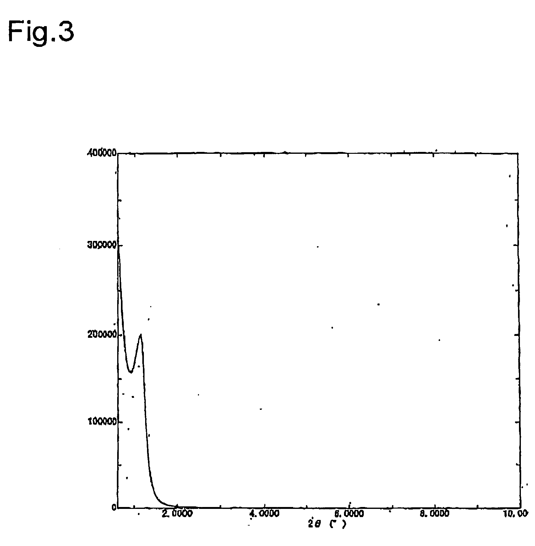
Synthesis of Thin Film of BiPh-HMM

[0106]First, a triblock copolymer P123 ((EO)20(PO)70(EO)20: surfactant: 0.40 g, 0.069 mmol) was dissolved in a mixed liquid of ethanol (3.0 g), water (0.18 g, 10 mmol) and 2 M HCl aqueous solution (5.0 μl, 0.010 mmol) to obtain a mixed solution. Then, 4,4′-bis(triethoxysilyl)biphenyl (0.598 g, 1.25 mmol) was added dropwise into the obtained mixed solution. Thereafter, the mixture was stirred at room temperature for 21 hours to obtain a reaction solution. Subsequently, ethanol (2.0 g) was added to the obtained reaction solution to obtain a biphenyl silica sol solution. Then, the sol solution was spin-coated (4000 rpm, 10 s) on a glass plate or a silica glass. Subsequently, the sol was dried at room temperature for one day to obtain a spin-coat thin film. The temperature of the obtained spin-coat thin film was increased from room temperature to 250° C. over 6 hours. Thereafter, the temperature was maintained at 250° C. for 2 hours. Then, the P123 (sur...

synthesis example 3

Synthesis of 4,4′-bipyridine Derivative

[N,N′-bis(3-(trimethoxysilanyl)propyl)-4,4′-bipyridinium diiodide])

[0108]First, 4,4′-bipyridyl (1.80 g, 11.0 mmol), and (3-iodopropyl)trimethoxysilane (7.02 g, 24.2 mmol) were dissolved in acetonitrile (25 ml) in an argon atmosphere to obtain a mixed solution. Then, the obtained mixed solution was stirred at 40° C. for 7 hours. Thereafter, the solution was stirred while heating at 70° C. for 18 hours. Furthermore, it was stirred while heating at 85° C. for 24 hours. Subsequently, the precipitate obtained in the above manner was washed with dichloromethane, and dried in vacuum to obtain 7.62 g of 4,4′-bipyridine derivative (N,N′-Bis(3-(trimethoxysilanyl)propyl)-4,4′-bipyridinium diiodide).

[0109]The structure of 4,4′-bipyridine derivative obtained in the above manner was recognized by 1H-NMR. The obtained results are shown below;

[0110]1H-NMR (500 MHz, D2O): δ 8.98 (d, 4H, J=6.7 Hz), 8.41 (d, 4H, J=6.7 Hz), 4.60 (t, 4H, J=7.3 Hz), 3.20 (s, 18H), 2...


PUM

PropertyMeasurementUnit
pore diameteraaaaaaaaaa
pore wall thicknessaaaaaaaaaa
pHaaaaaaaaaa

Abstract

A light energy conversion material, comprising:
    • a porous material including an electron donor in a skeleton thereof; and
    • an electron acceptor disposed in at least one portion among a pore, the skeleton and the outer circumference of the porous material.

Description

BACKGROUND OF THE INVENTION[0001]1. Field of the Invention[0002]The present invention relates to a light energy conversion material.[0003]2. Related Background Art[0004]Studies on a light energy conversion material have so far been made. The light energy conversion material utilizes a photo-excited electron transfer reaction in which an electron is transferred from an electron donor to an electron acceptor in accordance with the absorption of light energy.[0005]For example, Japanese Unexamined Patent Application Publication No. 2002-110260 (JP 2002-110260 A) discloses a light energy conversion material including a photoactive pigment, an electron donor, an electron acceptor, and a porous material having a pore with a pore wall thickness of 2 nm or less. The photoactive pigment is disposed inside or outside the pore. At least one of the electron donor and the electron acceptor is disposed inside the pore. Additionally, the electron donor and the electron acceptor are not disposed dir...

Claims


Application Information

Patent Timeline
Patent Type & Authority Applications(United States)
IPC IPC(8): C09K3/00
CPCC09K11/06C09K2211/1007C09K2211/1014H01G9/2027Y02E10/542H01G9/20H01G9/2031
Inventor INAGAKI, SHINJIAOKI, MASAOYAMANAKA, KEN-ICHINAKAJIMA, KIYOTAKAOHASHI, MASATAKA
Owner TOYOTA CENT RES & DEV LAB INC
Why Eureka
Try Eureka