High frequency power amplifier circuit and electronic component for high frequency power amplifier
a high frequency power amplifier and electronic component technology, applied in the direction of low noise amplifiers, amplifiers with field-effect devices, amplification control device circuits, etc., can solve the problems of increasing power consumption, increasing costs, and affecting the performance of the amplifier, so as to improve the high frequency power amplifying characteristic, reduce the scattering of high frequency power amplifying characteristics between chips, and improve the effect of high frequency power amplifying characteristics
- Summary
- Abstract
- Description
- Claims
- Application Information
AI Technical Summary
Benefits of technology
Problems solved by technology
Method used
Image
Examples
embodiment 1
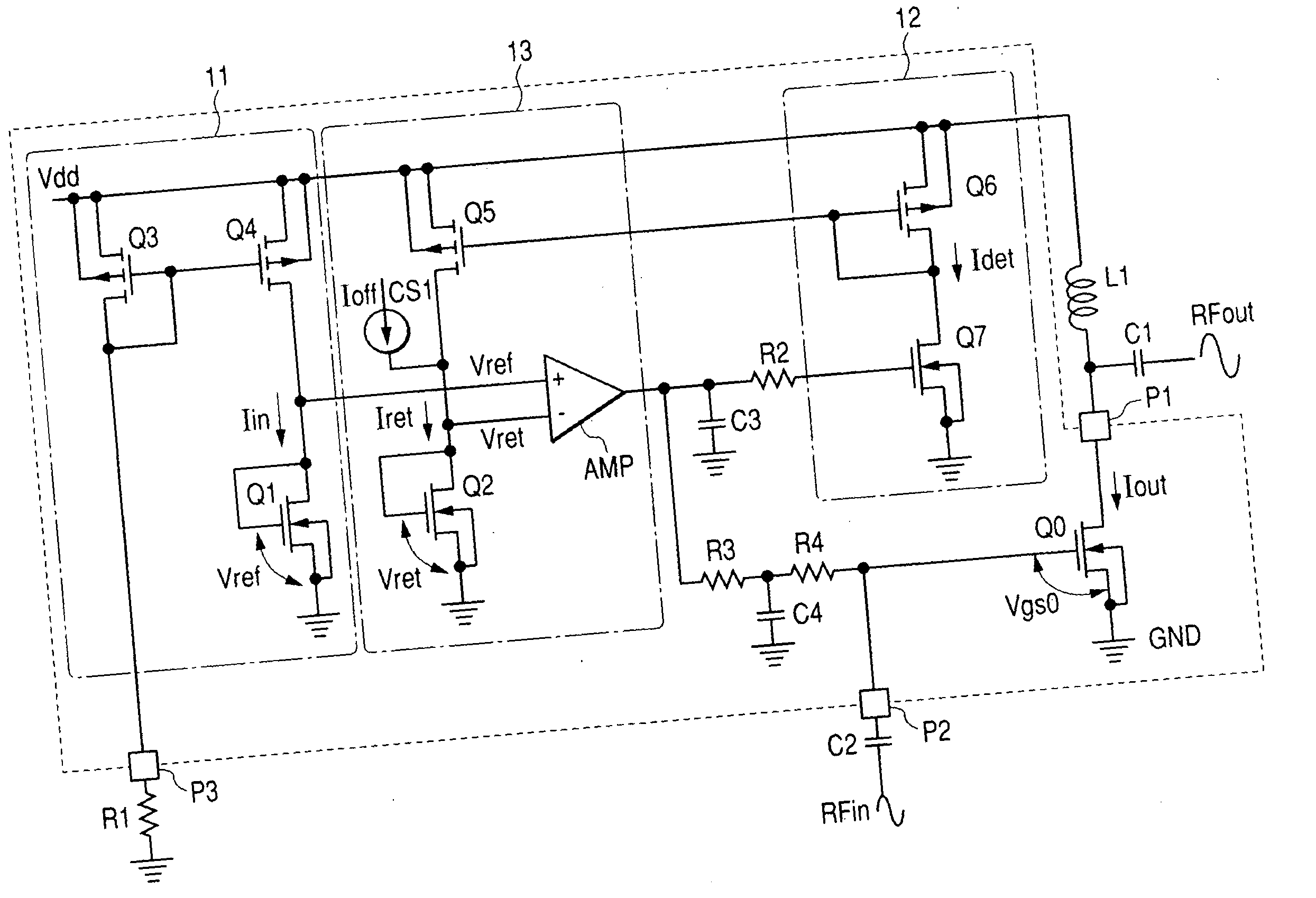
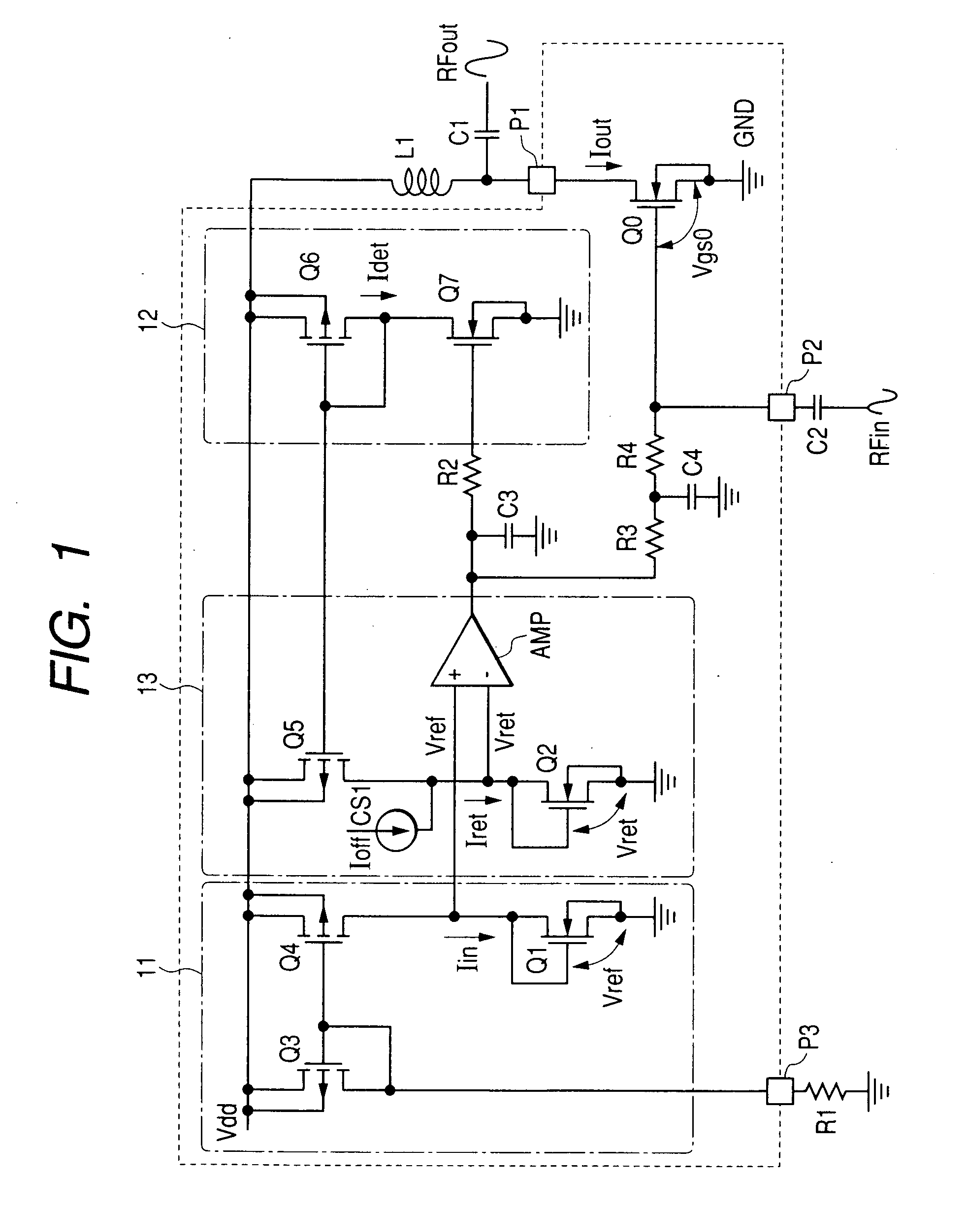
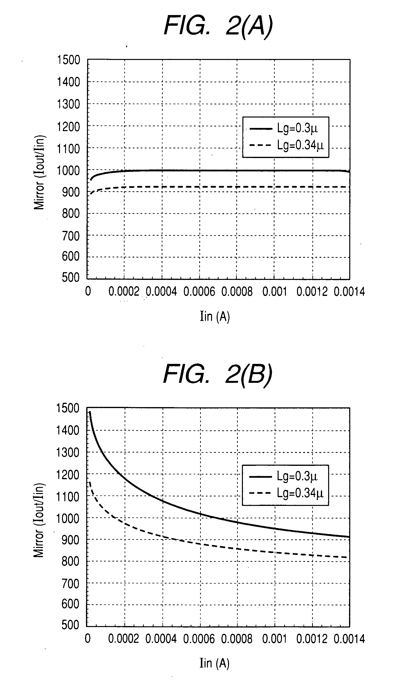
[0073]FIG. 1 shows rough composition of a first embodiment of a high frequency power amplifier circuit according to the present invention. Although not limited in particular, for example, the three high frequency power amplifier circuits having such composition as the embodiment of FIG. 1 are connected in a cascade, and mounted on an insulating substrate, such as a ceramic substrate, together with an external resistive element or a capacitive element, thereby constructing an RF power module (refer to FIG. 9 and FIG. 10). Further, cascade connection means that the three power amplifier circuits are connected so that the previous-stage high frequency output is input to the next-stage input pin. The high frequency power amplifier circuit of each stage is the same as FIG. 1 as the composition respectively, but differs in the size (gate width) of an amplifying FET. An FET of a broader size is used in the order of the first stage, second stage, and third stage. In the FET of this embodime...
embodiment 2
[0103] Next, a second embodiment of a high frequency power amplifier circuit according to the present invention is described with reference to FIG. 3.
[0104] A cellular phone of a GSM (global system for mobile communication) method is constructed so that the output power of the high frequency power amplifier circuit can be controlled by the output control voltage Vapc. FIG. 3 is an embodiment of the high frequency power amplifier circuit in which the output power control by such a Vapc is enabled. FIG. 3 differs from the high frequency power amplifier of the embodiment of FIG. 1 in that a bias current applied to the amplifying FET Q0 is kept constantly by specifying the current Iin applied from the constant current circuits (Q3 and Q4) that construct the reference circuit 11 to the amplifying FET Q1 to be a predetermined current value (fixed). To the contrary, in this embodiment (FIG. 3), the idle current Iout applied to the amplifying FET Q0 varies by allowing the reference bias ci...
embodiment 3
[0109] Next, a third embodiment of a high frequency power amplifier circuit according to the present invention is described with reference to FIG. 5.
[0110] This embodiment allows the high power amplifier circuit of the example of FIG. 3 to have two semiconductor chips and to provide a detection circuit (current sense circuit) for detecting output power (Power). The output power detection circuit in this embodiment has a detecting FET Q9 in which the same voltage as the voltage input to the gate pin of the amplifying FET Q0 is input to the gate pin through a resistor R5, a current mirror circuit 15 that transfers the drain current applied to the FET Q9, and an external resistor R6 that converts the current transferred from the current mirror circuit 15 into a voltage.
[0111] The FET Q9 for detecting output power is an element of the same characteristic having the same gate length formed in the same process as the amplifying FET Q0 and is formed so as to have a smaller gate width tha...
PUM
 Abstract
Description
Claims
Application Information
 - R&D
- Intellectual Property
- Life Sciences
- Materials
- Tech Scout
- Unparalleled Data Quality
- Higher Quality Content
- 60% Fewer Hallucinations
Browse by: Latest US Patents, China's latest patents, Technical Efficacy Thesaurus, Application Domain, Technology Topic, Popular Technical Reports.
© 2025 PatSnap. All rights reserved.Legal|Privacy policy|Modern Slavery Act Transparency Statement|Sitemap|About US| Contact US: help@patsnap.com


