Coupling-enhanced surface etched gratings

a technology of etched gratings and couplings, which is applied in the field of integrated photonics, can solve the problems of not necessarily the optimum solution from fabrication complexity, the device design of etched gratings and the technique is not particularly low complexity or high yield. achieve the effect of enhancing the coupling of the effective ridge lc-seg

Active Publication Date: 2008-03-20
ONECHIP PHOTONICS
View PDF1 Cites 8 Cited by
  • Summary
  • Abstract
  • Description
  • Claims
  • Application Information

AI Technical Summary

Benefits of technology

[0014] The object of the present invention is to provide a solution to the coupling enhancement in the effective-ridge LC-SEG waveguide structures. The objective is achieved by replacing the waveguide structure having one effective ridge, formed by the periodic continuous trenches, w

Problems solved by technology

On the other hand, this may be not necessarily the optimum solution from the fabrication complexity and yield points of view.
However, it requires re-growth to complete the device fabrication and is very demanding as it concerns to the quality of the interface between the etched corrugated surface and newly grown epitaxial material, which injection current should pass through with minimal loss.
Therefore, this technique is not a particularly low-complexity or high-yield solutio

Method used


Image

  • Coupling-enhanced surface etched gratings
  • Coupling-enhanced surface etched gratings
  • Coupling-enhanced surface etched gratings

Examples


Embodiment Construction

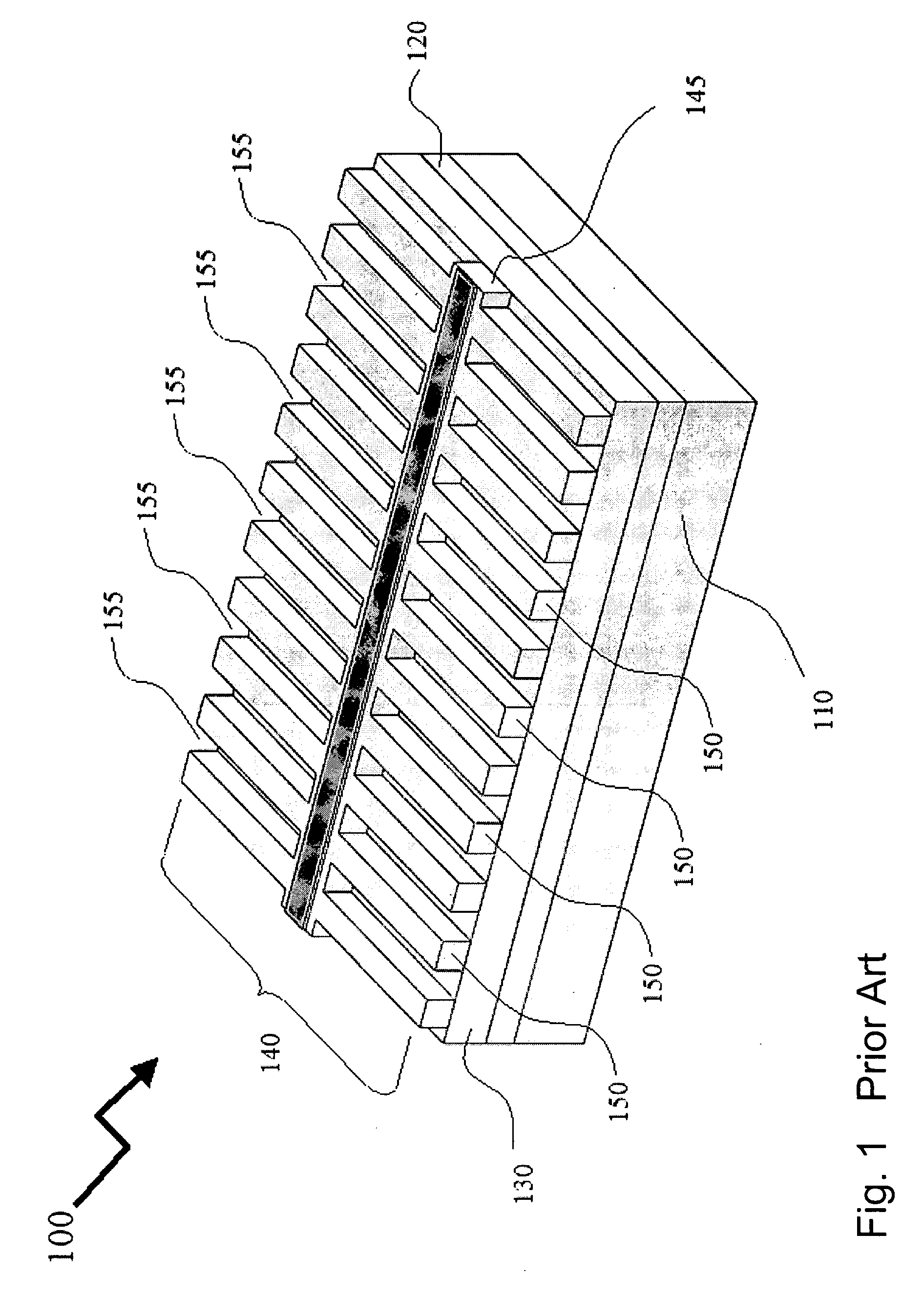
[0036]FIG. 1 illustrates a schematic three-dimensional view of a prior art embodiment of an effective-ridge LC-SEG structure 100. Shown are a waveguide layer structure comprising lower cladding layer 110, core waveguiding layer 120, and upper cladding layers 130 and 140. The LC-SEG waveguide structure is defined by the parallel continues trenches etched in the top portion of the upper cladding layer 140 on the both sides of the narrow strip of the intact material 145, which acts as the (only) effective ridge providing the lateral confinement to the slab waveguide modes propagating in the direction perpendicular to the trenches. This is caused by the difference in refractive indices between the intact and etched parts of the LC-SEG, 150 and 155, respectively, in which the former always has the higher refractive index than the latter for any wavelength within a certain predetermined range of the operating wavelengths. Periodicity of the trenches results in a periodical perturbation of...


PUM


Abstract

The invention describes the method and apparatus for enhancement of coupling efficiency in effective-ridge laterally-coupled surface-etched grating waveguide structures, where a slab waveguide has a sequence of the periodic parallel segmented trenches etched from its top surface, such that the segments of intact material having higher refractive index than that in the surrounding segments of periodic trenches form the effective ridges which confine the optical field in and around these ridges, on one hand, and provide bidirectional coupling for the confined modes experiencing Bragg reflection from the segments of the periodic trenches, on the other. The invention discloses the designs of the multiple effective ridge laterally coupled surface-etched grating waveguide structures, which enhances the coupling efficiency as compared to a conventional single effective ridge grating design because of an intended dilution of the lateral confinement caused by the multiple effective ridges, resulting in an increase of the optical mode's overlap with the surface etched grating formed everywhere outside the effective ridges.

Description

FIELD OF THE INVENTION [0001] The invention relates generally to the field of integrated photonics, and more particularly to integrated waveguide devices using waveguide Bragg gratings. BACKGROUND OF THE INVENTION [0002] Explosive growth of the optical communication traffic in recent years, driven by bandwidth hungry applications and progress in transmission technologies alike, has greatly contributed to ever-increasing demand for higher capacity optical networks offering more flexibility at lower cost. Two different yet complimentary trends are becoming more and more evident in this respect. First, deep penetration of the optical fiber into the access networks and, second, greater demand for capacity, bandwidth provisioning and agility back up into the upper layer networks. Both require massive deployment of the optical gear that drives the traffic along the fiber links, on a scale not seen in earlier generation networks. Specifically, optical transceivers, which receive downstream...

Claims


Application Information

Patent Timeline
IPC IPC(8): G02B6/34
CPCG02B6/124H01S5/1237H01S5/22
Inventor TOLSTIKHIN, VALERYPIMENOV, KIRILL
Owner ONECHIP PHOTONICS
Why Eureka
Try Eureka