
Method for Steam Reforming Carbonaceous Material

Active Publication Date: 2008-05-15
BRADAM GRP LLC
View PDF4 Cites 2 Cited by
  • Summary
  • Abstract
  • Description
  • Claims
  • Application Information

AI Technical Summary

Benefits of technology

[0011]Commercial lime (i.e. calcium oxide and / or a bicarbonate of soda) is mixed in with the shredded MSW. When the steam reforming is taking place, the calcium in the lime reacts with halogens that are released from the MSW, forming calcium salts that are generally benign. This feature is important because removing halogens in this early stage is simpler and less costly than removing them later downstream, which would typically involve using sorbent bed cleaning units. This also avoids the opportunity for these halogens to form acid vapours and / or the more highly toxic dioxins and furans, if these constituents come into contact with oxygen while at elevated temperatures during the steam reforming process. (The formation of dioxins and furans is one of the major problems with most incineration systems). Because the halogens react very readily with the lime, they are not available to form acid vapours and / or dioxins and furans. Note that with steam reforming, where most of the atmospheric air and hence oxygen is purged from the incoming waste stream (as described below), there will be little opportunity for conversions to the toxic dioxins and furans as there most certainly would be for combustion and incineration systems.
[0032]Excess CO2 and steam from the GTL, or the CO2 and steam from the fuel cell, can be channeled into a synergistically located greenhouse. This results in the sequestering of carbon in a manner beneficial to the environment. Meanwhile, the growth of fruit, vegetables, or other agricultural, horticultural or forest products within the greenhouse is enhanced. Also, the CO2 may be captured and used for other commercial uses or introduced into a conversion process for the production of useful by-products.

Problems solved by technology

(The formation of dioxins and furans is one of the major problems with most incineration systems).
Because the halogens react very readily with the lime, they are not available to form acid vapours and / or dioxins and furans.

Method used


Image

  • Method for Steam Reforming Carbonaceous Material
  • Method for Steam Reforming Carbonaceous Material
  • Method for Steam Reforming Carbonaceous Material

Examples


Embodiment Construction

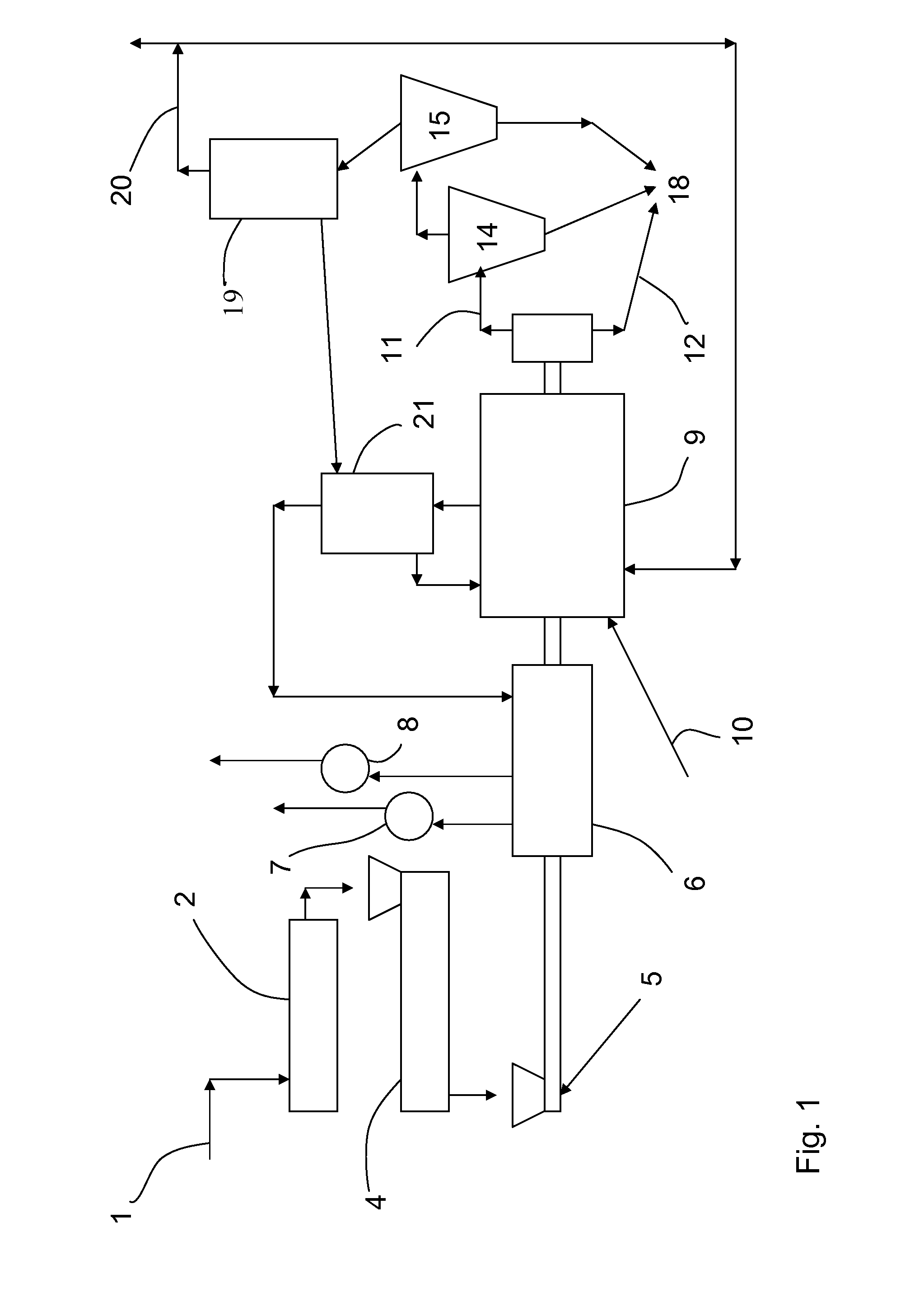
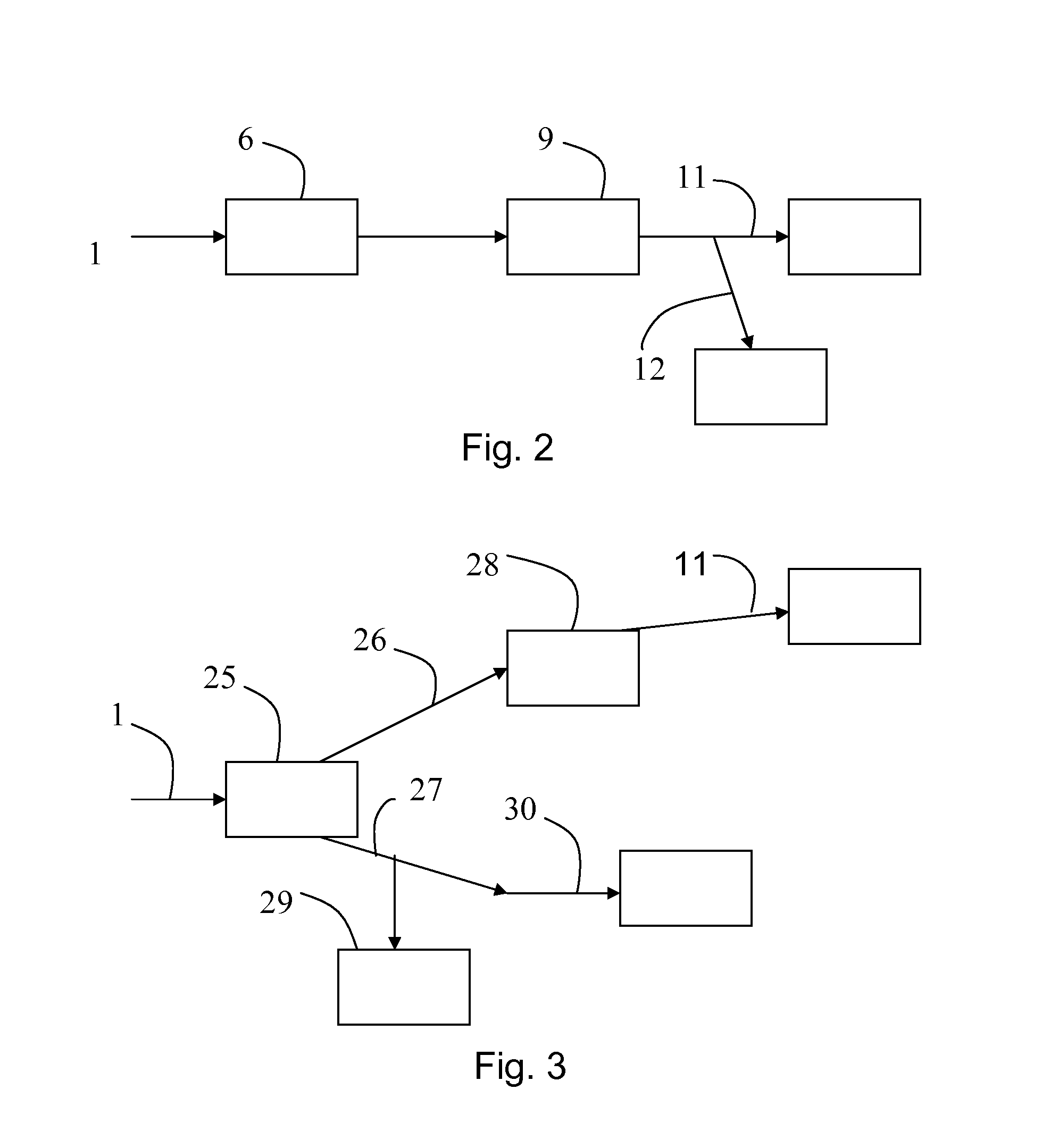
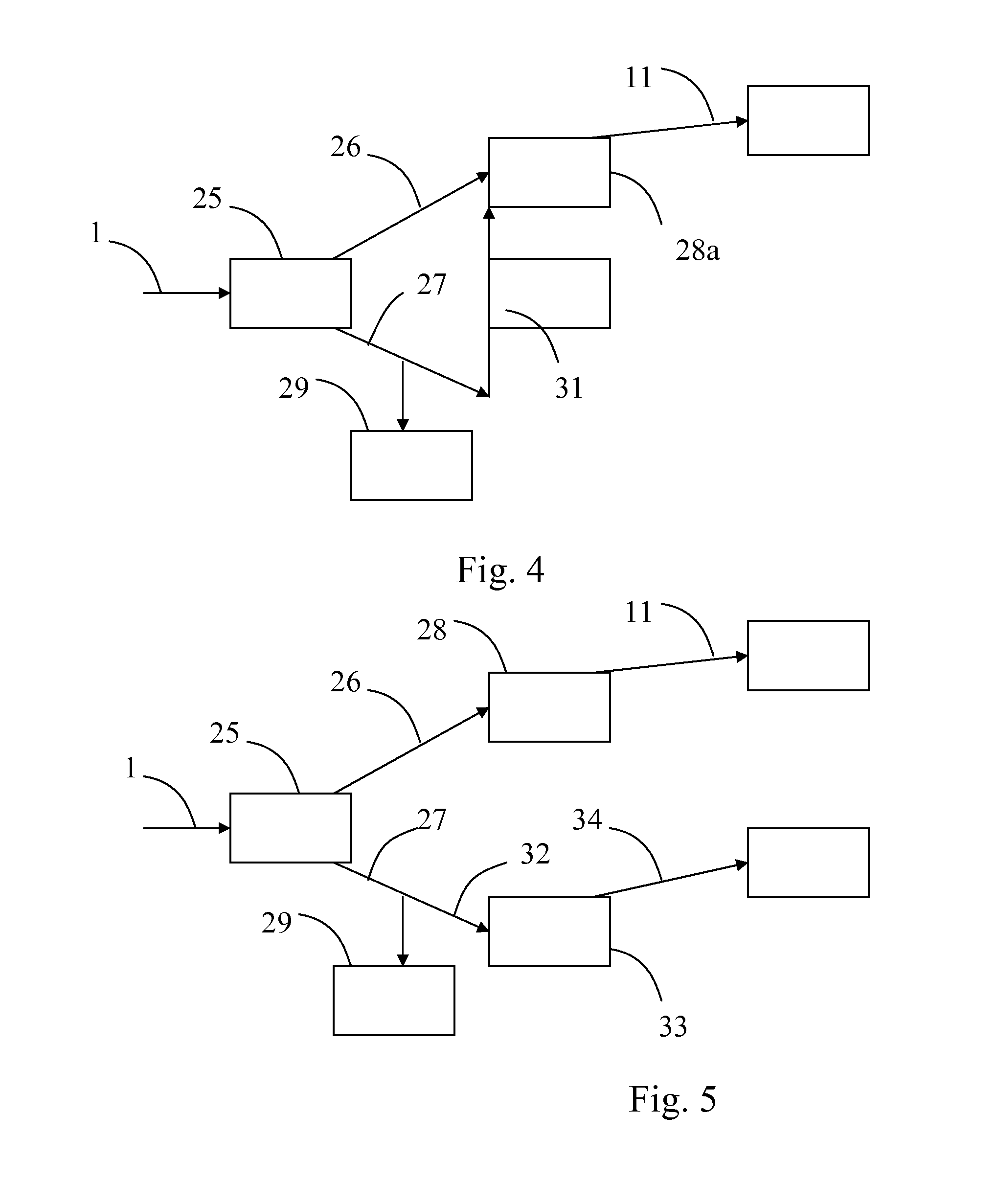
[0045]FIG. 1 is a schematic diagram of a preferred embodiment of the single stream, one-stage process. The CM input 1 is continuously fed into an auger or screw conveyor 2, where it is shredded in a shredder 4. The CM may optionally be pre-treated by passing through a pre-heater or rotary drum dryer 6 before being fed into the steam reforming rotary kiln 9. This serves to do one or more of the following: remove excess moisture from the CM, generate steam, and warm up the shredded CM (to approximately 250° C.) in readiness for the steam reforming reaction. Where necessary, make-up water and / or steam 5 is added to the shredded CM. As previously mentioned, it is advantageous to provide for a continuous feed of high temperature steam to purge the CM entering the steam reforming kiln 9 of air, (in particular, of oxygen and nitrogen). The pre-heater 6 is provided with one or more flue gas vents 7 and one or more steam vents 8 for releasing excess steam. The CM is then fed into the steam r...


PUM


Abstract

A method for steam reforming carbonaceous material into a synthesis gas by using a single stage process of heating the carbonaceous material in a rotary kiln at an elevated reforming temperature so that the carbonaceous material undergoes substantially complete conversion to synthesis gas or by using a dual stream, multiple-stage process of heating carbonaceous material to a reforming temperature, below that at which metallic materials will typically vaporize, to form gaseous and solid materials; further reforming the gaseous materials in a second stage reforming kiln at an elevated reforming temperature to form synthesis gas; and separating carbon char from the solid material for further processing.

Description

FIELD OF THE INVENTION[0001]This invention relates generally to steam reforming technology.BACKGROUND OF THE INVENTION[0002]Steam reforming processes are known, and are used for converting various kinds of carbonaceous materials into useful commodities. The term carbonaceous material (“CM”) as used herein includes any carbonaceous material, including: municipal solid waste (“MSW”); industrial, commercial and institutional waste (“ICIW”); medical waste; coal; coal waste; wood waste; sawdust; forest product waste; agricultural waste; sewage; liquid waste; hazardous waste; waste oil and oil by-products; electronic waste and other similar carbonaceous substances; also included are opportunity materials such as incineration and / or combustion ash, which may be used in order to achieve conversion upgrade opportunities in existing incineration plants.[0003]In the steam reforming process, carbonaceous material is placed in a steam reforming kiln, which usually comprises a drum or kiln that i...

Claims


Application Information

Patent Timeline
IPC IPC(8): C01B3/02
CPCC10J3/005C10J3/06C10J3/20C10J3/721C10J2200/158C10K3/006C10J2300/092C10J2300/0946C10J2300/0973C10J2300/1884C10J2300/0916Y02P20/145C10J3/16
Inventor ZWIERSCHKE, JAYSONDUECK, ERNEST GEORGE
Owner BRADAM GRP LLC
Learn More