Production of Synthesis Gas from Biomass and Any Organic Matter by Reactive Contact with Superheated Steam

a technology of biomass and superheated steam, which is applied in the direction of combustible gas production, gasifier mechanical details, sustainable manufacturing/processing, etc., can solve the problems of ineffective direct burning of biomass, large utilization of co-produced heat, and difficult burning, so as to improve the efficiency of the reactor

Active Publication Date: 2008-07-17
PULKRABEK PETER +1
View PDF9 Cites 30 Cited by
  • Summary
  • Abstract
  • Description
  • Claims
  • Application Information

AI Technical Summary

Benefits of technology

[0033]The reactor for achieving this employs a high-temperature vessel, e.g. quartz glass. Water in the form of low-temperature steam, enters through an inlet feed tube and proceeds through a heater sleeve, i.e., hot zone, which can be heated to the required temperature (e.g., 1000° C.) by means of an RF induction coil. The resultant superheated steam exits this hot zone into the interior of the vessel. The biomass is introduced, e.g., with a screw drive, to the top at a controlled rate so the amount of biomass is matched to the volume of superheated steam. Flash Hydropyrolysis™ occurs on contact. The hot products of the initial Flash Hydropyrolysis™ enter a second hot zone that maintains the biomass and steam at the required temperature under anaerobic conditions. The synthesis gas then exits at the end of the second hot zone as a mixture of simple gases: hydrogen, carbon monoxide, and carbon dioxide. The ratio of the combustible gases can be regulated by controlling the water input, the temperature of the superheated steam, and the rate of feed of the biomass material. Much of the thermal energy in the superheated steam is used in converting the biomass and water into the energy gases. However, there is still considerable thermal energy remaining in the exiting gases, and this can be used to preheat / boil the incoming water and to dry and pre-heat the entering biomass. Drying and pre-heating the biomass feed will improve efficiency of the reactor, but is not an absolute necessity for the process to go forward.

Problems solved by technology

The direct burning of biomass has been an ineffective way of obtaining its energy.
The biomass materials, e.g., hay, straw, leaves, seed hulls, etc., are complicated materials that release gases rather quickly during the burning process, but leave the carbon component (typically 70% to 80% by weight), which is difficult to burn.
In addition, especially during the growing season, there is a problem with utilization of large amounts of co-produced heat.
Because only the sweet or food parts of the plant are available, which constitute only a small portion of the plant, ethanol fermentation is not a particularly effective use of the biomass energy content.
Furthermore, with existing ethanol technology, only about one-third of fermentable sugars are converted into ethanol.
While this can be an effective means of using the oily component of the plant, there is only a small available yield of seed oils.
Also, since only a small portion of the plant is used, this does not present an effective means of utilizing the fibrous component of biomass.
Yields from energy farming currently in place will not be sufficient for estimated national energy consumption unless means are provided to utilize the whole plant for energy production.
However, unlike brown coal, the biomass source is an entirely renewable resource, contributing no new carbon dioxide, and its sulfur content is only a very small fraction of that found in coal.

Method used


Image

  • Production of Synthesis Gas from Biomass and Any Organic Matter by Reactive Contact with Superheated Steam
  • Production of Synthesis Gas from Biomass and Any Organic Matter by Reactive Contact with Superheated Steam
  • Production of Synthesis Gas from Biomass and Any Organic Matter by Reactive Contact with Superheated Steam

Examples


Embodiment Construction

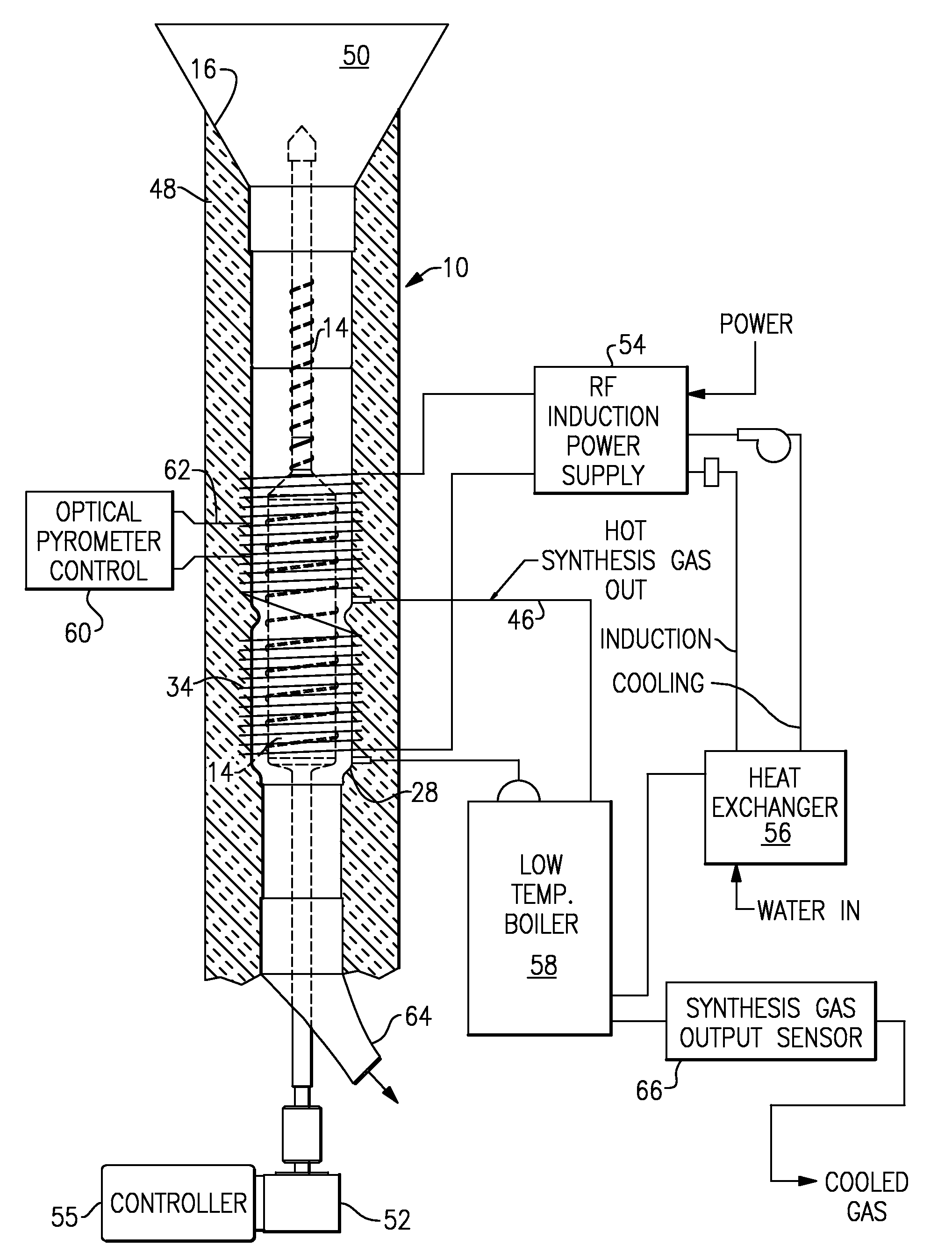
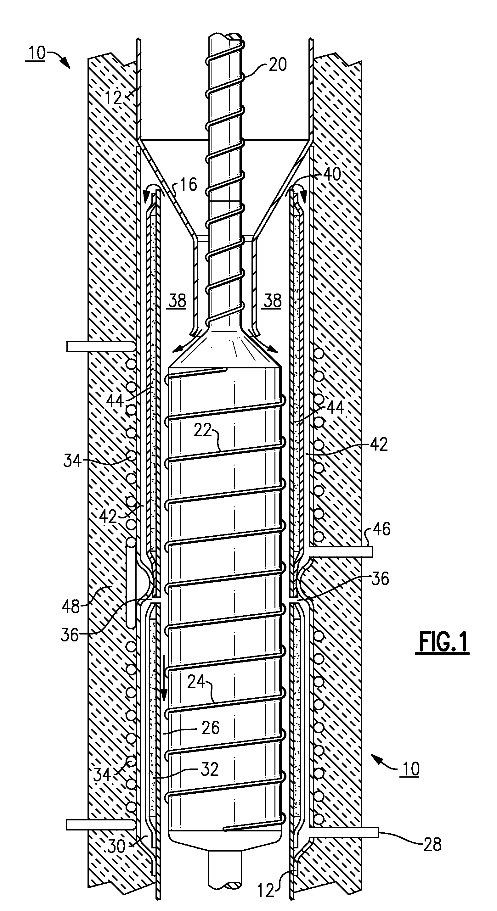
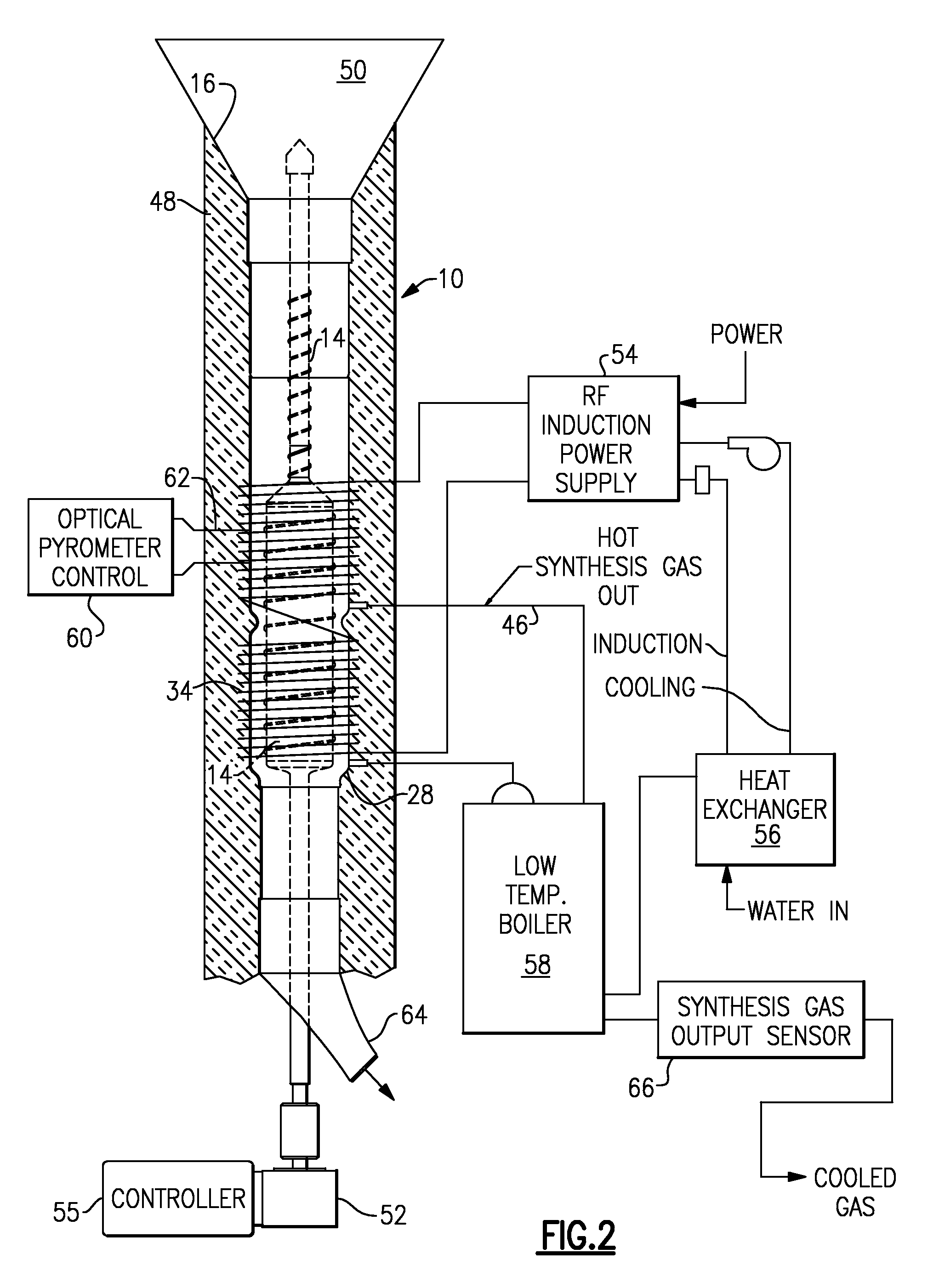
[0039]With reference to the Drawing, and initially to FIG. 1, a Flash Hydropyrolysis™ reactor 10 is shown for carrying out a continuous or batch process generation of synthesis gases from biomass matter of the type described hereinabove. The biomass is chopped when harvested to a size standard, and is allowed to pre-dry. The reactor is formed of a generally tubular quartz envelope 12, which houses a rotor 14 as shown which rotates to bring the biomass particles into contact with the superheated steam as explained. The upper end of the envelope can be much higher as indicated by the break lines, and the inlet for bringing in fresh biomass is not shown here.

[0040]There is a neck or funnel 16 surrounding a thinner portion 18 of the rotor, with the rotor 14 widening beneath the lower mouth of the funnel 16. The bottom of the vessel or envelope 12 extends down, as indicated at the lower break lines, and can receive a considerable volume of the ash. Threads, vanes or screws 20, 22, 24 are...


PUM

PropertyMeasurementUnit
temperatureaaaaaaaaaa
temperaturesaaaaaaaaaa

Abstract

Organic matter, i.e., biomass, fibrous plant matter, organic chemicals or organic waste, or other carbon-based matter is converted to synthesis fuel gas by reactive contact with superheated steam at a temperature of about 200 to 2000 degrees C., typically 500 to 1700 degrees. A reactor has a generally tubular envelope, a rotor within the envelope, and hot reaction spaces disposed annularly within the wall of the tubular envelope. The steam and biomass particles can be heated to the required temperatures by RF induction. The product gases include H2, CO, and CO2 in ratios controlled by a programmable controller. Control of temperature, biomass feed rate and water flow preselects the output synthesis gas mix. The synthesis gas may be processed into portable liquid fuels, or can be used directly in a fuel cell.

Description

[0001]Applicants claim priority benefits under Title 35, United States Code, Sec. 119(e) of U.S. Provisional Patent Application Ser. No. 60 / 880,490, filed Jan. 16, 2007.BACKGROUND OF THE INVENTION[0002]This invention relates to conversion of biomass, i.e., fibrous plant matter, carbon waste products and organic chemicals (including any toxic compounds such as chlorinated organics, PCBs, etc.) into synthesis gas (useful fuel gases; namely, hydrogen gas and carbon monoxide) and is more particularly concerned with an effective process for converting all plant matter as well as all dried organic material by contact with superheated steam (Flash Hydropyrolysis™).[0003]Biomass is a term used to refer to any material of agricultural origin, and a number of candidate materials that are biomass based can be considered possible feedstock for different energy producing procedures. Some common processes for energy extraction have employed various forms of fibrous plant matter, such as wood chip...

Claims


Application Information

Patent Timeline
Patent Type & Authority Applications(United States)
IPC IPC(8): C07C4/04C10B1/04C10B49/00
CPCC10J3/20C10J2200/09C10J2200/158C10J2300/1892C10J2300/0973C10J2300/123C10J2300/1884C10J2300/0916Y02P20/145Y02P20/129Y02P20/10
Inventor PULKRABEK, PETERCOFFEY, CALVIN T.
Owner PULKRABEK PETER
Why Eureka
Try Eureka