Microwave plasma apparatus and method for materials processing

a technology of microwave plasma and material processing, which is applied in the direction of plasma technique, manufacturing tools, electric/magnetic/electromagnetic heating, etc., can solve the problems of harming the properties of the end-point ceramic body, unable to achieve the ideal deposition conditions of current spray technology, and difficult to achieve uniform droplet temperature. , to achieve the effect of enhancing the coupling of microwave radiation, minimizing leakage of microwave radiation, and high temperatur

Active Publication Date: 2008-07-24
6K INC +1
View PDF50 Cites 71 Cited by
  • Summary
  • Abstract
  • Description
  • Claims
  • Application Information

AI Technical Summary

Benefits of technology

[0012]The microwave plasma apparatus is designed to enhance coupling of the microwave radiation to the process gas and to minimize leakage of the microwave radiation from the apparatus.
[0013]The plasma jet is stabilized within the plasma chamber either by viscous contact with a swirling flow of a shrouding gas, or by adhesion to an emitter rod, or by both methods.

Problems solved by technology

Such ideal deposition conditions cannot be achieved with current spray technologies.
In particular, uniform droplet temperature has proven very difficult to achieve.
However, semi-pyrolized or un-melted inclusions due to varying particle sizes can lead to inhomogeneities including voids that harm the properties of the end point ceramic body.
Ceramics being generally brittle have mechanical properties strongly affected by flaws.
Particles injected to the plasma jet external to the plasma torch necessarily enter the plasma jet off-axis, thereby introducing local non-uniformity to the entrainment of the particles in the plasma jet.
Moreover, entrainment of ambient gas into the plasma jet at the plasma torch exit results in a highly non-uniform radial and axial temperature profile external to the plasma torch.
Accordingly, particles injected to the plasma jet external to the plasma torch are not uniformly entrained in or heated by the plasma jet.
It is noted that internal structures required for axial injection are difficult to make compatible with internal structural constraints related to establishing and maintaining a DC a

Method used


Image

  • Microwave plasma apparatus and method for materials processing
  • Microwave plasma apparatus and method for materials processing
  • Microwave plasma apparatus and method for materials processing

Examples


Embodiment Construction

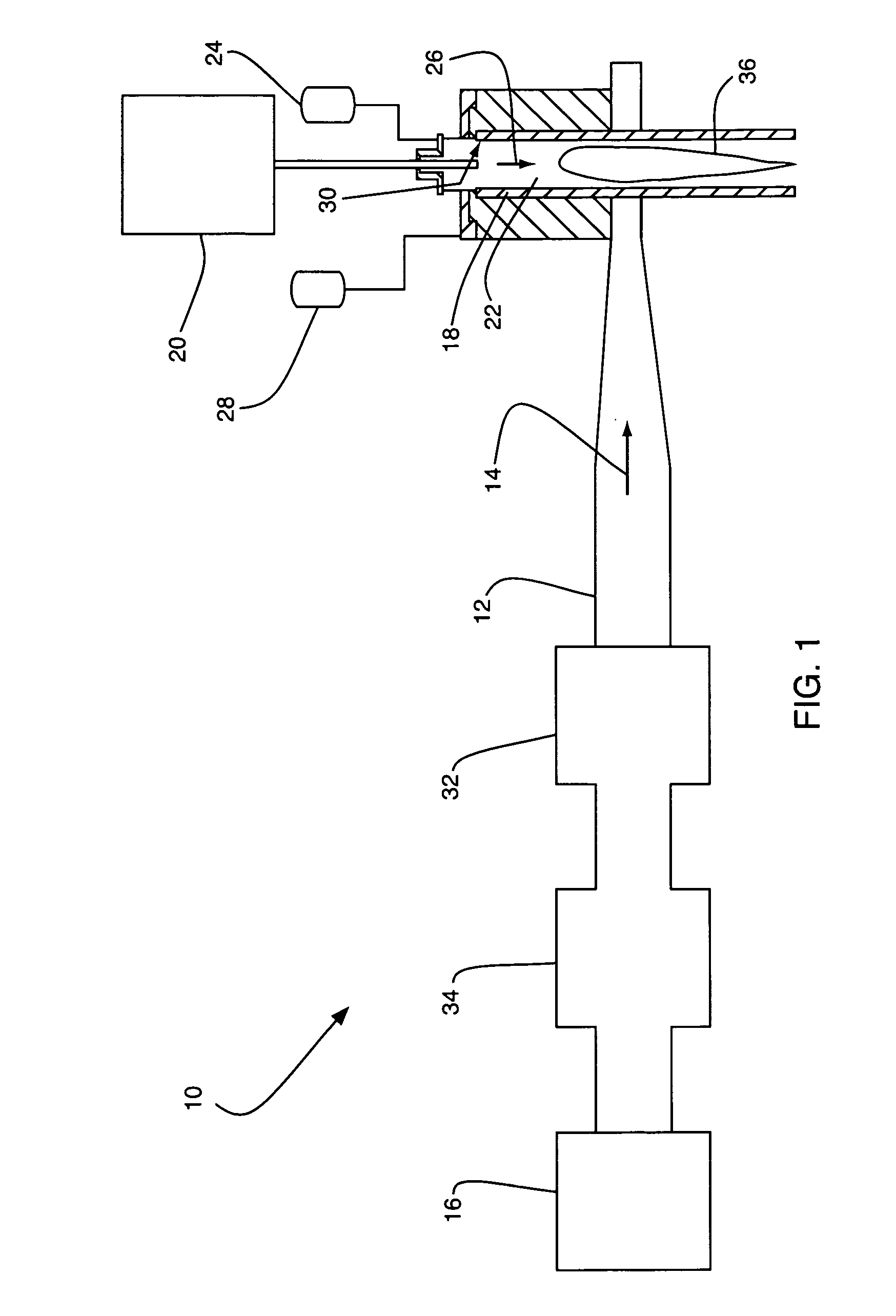
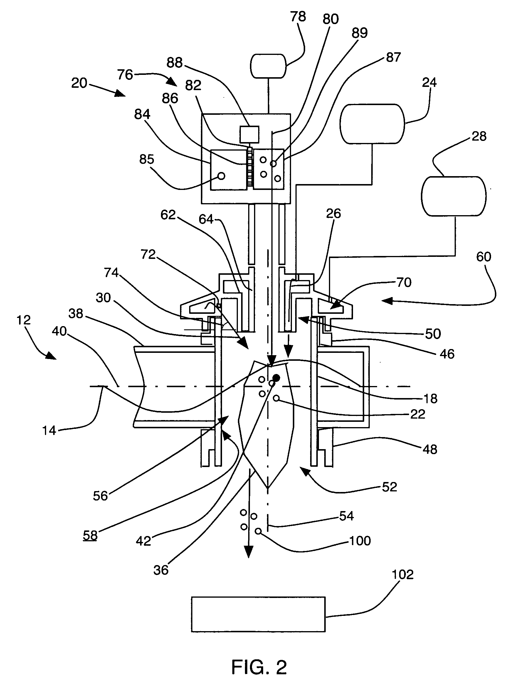
[0022]Referring to FIG. 1, a microwave plasma apparatus 10 for material processing, in accordance with an embodiment of the present invention, includes a waveguide 12 that guides microwave radiation 14 from a microwave source 16 to a plasma chamber 18 that penetrates the waveguide 12. The apparatus 10 also includes a material feeding system 20 that feeds a process material 22 to the plasma chamber 18, a pressurized source 24 that supplies a process gas 26 to the plasma chamber 18, and a pressurized source 28 that supplies a shrouding gas 30 to the plasma chamber 18. The apparatus 10 further includes an impedance matching unit 32 that communicates with the microwave source 16 and the waveguide 12 to minimize reflection of the microwave radiation 14 from the plasma chamber 18 to the microwave source 16. The apparatus 10 can also include a reflected power protector 34 in communication with the waveguide 12. The reflected power protector 34 could be a waveguide circulator that deflects ...


PUM

PropertyMeasurementUnit
Flow rateaaaaaaaaaa
Volumeaaaaaaaaaa
Velocityaaaaaaaaaa

Abstract

A microwave plasma apparatus for processing a material includes a plasma chamber, a microwave radiation source, and a waveguide guiding microwave radiation from the microwave radiation source to the plasma chamber. A process gas flows through the plasma chamber and the microwave radiation couples to the process gas to produce a plasma jet. A process material is introduced to the plasma chamber, becomes entrained in the plasma jet, and is thereby transformed to a stream of product material droplets or particles. The product material droplets or particles are substantially more uniform in size, velocity, temperature, and melt state than are droplets or particles produced by prior devices.

Description

CROSS-REFERENCE TO RELATED APPLICATIONS[0001]The present application is entitled to the benefit of and hereby incorporates by reference essential subject matter disclosed by U.S. Provisional App. Ser. No. 60 / 881,357 filed Jan. 18, 2007.FIELD OF THE INVENTION[0002]The present invention relates to apparatuses and methods for plasma material processing and, more particularly, to apparatuses and methods for microwave plasma material processing.BACKGROUND OF THE INVENTION[0003]Thermal spray deposition of surface coatings has been used to form hard coatings on machine tools, thermal barriers on refractory surfaces, and hydrophobic layers on medical tools, paper mill rollers, or pharmaceutical equipment. In thermal spray deposition, molten droplets of a coating material impinge upon and adhere to a target surface. Ideal deposition conditions include substantial uniformity of droplet composition, size, velocity, and temperature. Such ideal deposition conditions cannot be achieved with curre...

Claims


Application Information

Patent Timeline
IPC IPC(8): H05B6/70
CPCC23C4/127H05H1/24C23C16/513C23C16/511H05H1/30C23C4/134B05B7/226
Inventor HADIDI, KAMALCETEGEN, BAKI M.JORDAN, ERICWOSKOV, PAUL
Owner 6K INC
Why Eureka
Try Eureka