
System and Method for Zero Emissions, Hydrogen Fueled Steam Generator

a technology of hydrogen fueled steam generator and system, which is applied in the field of system and method of generating steam, can solve the problems of not being able to produce carbon monoxide or carbon dioxide like previous fuels such as natural gas, methane, cellulose based, etc., and achieves the effects of reducing mechanical components, reducing the stress on mechanical components, and reducing the temperature of the reaction chamber

Inactive Publication Date: 2008-09-18
DOLAND GEORGE
View PDF0 Cites 12 Cited by
  • Summary
  • Abstract
  • Description
  • Claims
  • Application Information

AI Technical Summary

Benefits of technology

[0009]The invention presented here takes advantage of several features of the hydrogen oxidation reaction. First, this reaction is one of the most energetic binary reactions of two basic elements. It produces tremendous energy yet it takes very little to get the reaction started and it occurs spontaneously at relatively low temperatures. In the presence of a catalyst, such as platinum, spontaneous oxidation will occur at an even lower temperature. Therefore, in one embodiment of this invention, a catalyst is used to lower the combustion temperature to the point where very little nitrous oxide is created, even when air is used to provide the oxygen. Unlike complex hydrocarbon oxidation reactions, the hydrogen-oxygen reaction easily goes to completion, so the hydrogen fuel is efficiently converted to heat which is used to boil the water. The result of the combustion reaction is essentially water, with virtually no nitrogen compounds, and absolutely no carbon compounds. The resulting exhaust can be condensed to recover the water which enables the process to use the high heating value (HHV) for the hydrogen fuel.
[0011]In yet another embodiment of this invention, water is injected with the hydrogen and oxygen. The result is lowering the temperature of the reaction chamber. This reduces the stresses on the mechanical components, and lengthens the life of the steam generator. The steam generated in the reaction chamber by the vaporizing of the injected water is recovered to maintain the overall efficiency of the generator.
[0012]In yet another embodiment of this invention, the tubes are coated with material to reduce the effects on them when operated in an environment of hydrogen, oxygen, high temperature and water vapor. Coatings like titanium dioxide form a barrier which prevents hydrogen atoms from migrating through a metal surface and resulting in hydrogen embrittlement. Similarly, chromium surface coatings have been used as a barrier for water and steam related erosion. Also, ceramic and carbon coatings have been used as barriers against the effects of very high temperatures.
[0016]In yet another embodiment of this invention, a closed loop steam loop would be used with an open loop reaction system. This arrangement is similar to most package boilers produced today. Whether it is a fire tube or a water tube boiler, the reaction side is open with the flue gas venting to the atmosphere and the steam loop is a closed loop with condensate returned to the system elsewhere in the process. The difference between the prior art and this invention is the hydrogen fuel, the resulting lack of air pollution, and the addressing of the extremely harsh environment resulting from the fuel / oxidizer combination.

Problems solved by technology

Therefore, it cannot create carbon monoxide or carbon dioxide like previous fuels such as natural gas, methane (from Biomass and other sources), coal and coal based syngas, oil, wood, petroleum products and byproducts, cellulose based fuels and cellulose byproducts, slag, etc.
However, in the pure oxygen environment, only water can be produced as a result of the reaction.
The result is lowering the temperature of the reaction chamber.
This reduces the stresses on the mechanical components, and lengthens the life of the steam generator.

Method used


Image

  • System and Method for Zero Emissions, Hydrogen Fueled Steam Generator
  • System and Method for Zero Emissions, Hydrogen Fueled Steam Generator
  • System and Method for Zero Emissions, Hydrogen Fueled Steam Generator

Examples


Embodiment Construction

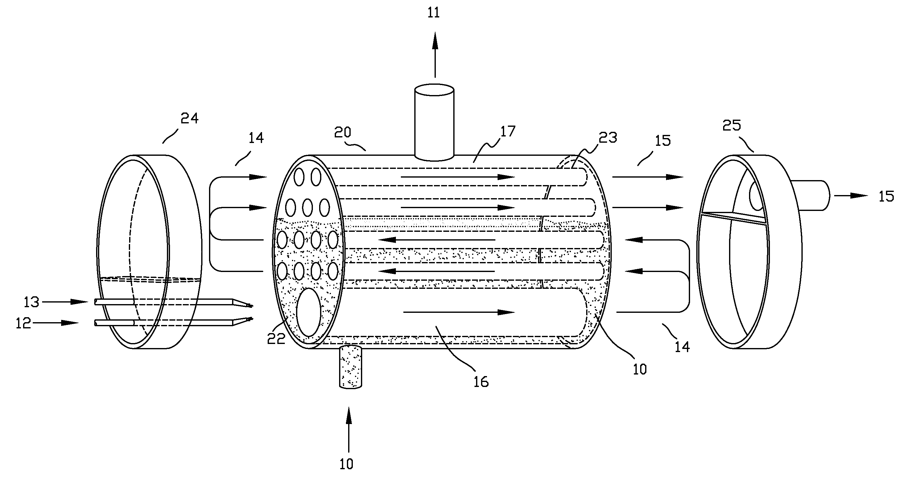
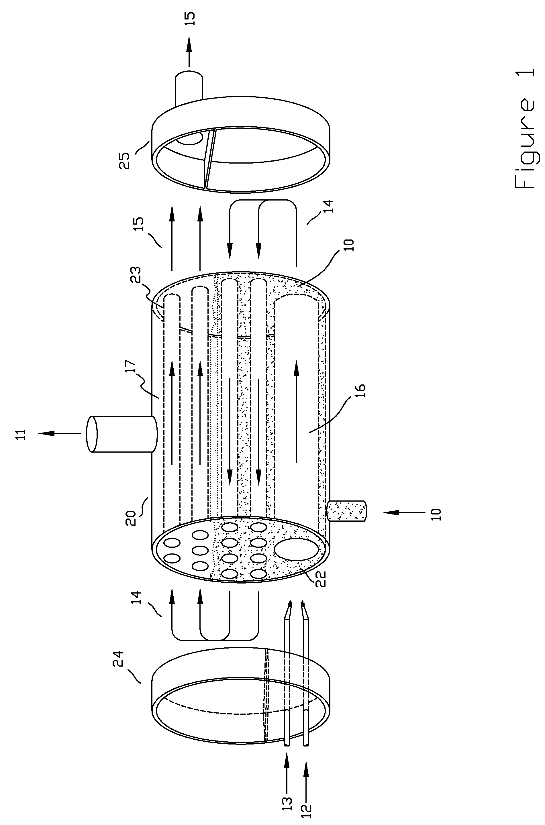
[0022]FIG. 1 illustrates one preferred embodiment of this invention wherein the steam generator is operates within a shell 20 with one head 24 fixed on the left end and the other head 25 fixed on the right end. The heads 24 and 25 are shown separated from the shell 20 for illustration purposes, so the path of the gasses and the divider plate within the heads can be more clearly understood. In operation the heads are affixed to the shell. The boiler tubes 23 are fixed at each end to the tube sheets 22.

[0023]In operation, water 10 enters the shell through the nozzle at the bottom of the shell. The controller maintains a fixed water level within the shell 20. Hydrogen 12 and oxygen 13 enter through conduits penetrating the left head 24. The hydrogen 12 and oxygen 13 react together in the reaction chamber 16. As these reaction gasses 14 combine together they move down the path shown by the arrows. The heat generated by the reaction, passes through the tube walls causing the water 10 to ...


PUM


Abstract

As we move towards a hydrogen economy or use hydrogen as an energy carrier, the need to get heat energy and steam out of the hydrogen is arising more frequently. This invention addresses that need without the atmospheric pollutants which would result from burning carbon based fuels or hydrogen freely in the air. Presented is an invention which has very high overall efficiency and generates no oxides of carbon and nearly zero nitrogen oxide compounds. The generated steam can be used for comfort heating, process heating, electric generation and other common applications requiring steam. The invention can also be used for generation of hot water. The process of steam generation is accomplished by precisely metering the mixing and oxidation of hydrogen and oxygen under controlled conditions. The result of this oxidation reaction is simply only water and heat, which are used to generate steam.

Description

FIELD OF INVENTION[0001]The present invention relates generally to generation of steam. More particularly, the present invention relates to a system and method of generating steam using hydrogen as the fuel source. The present invention generates no air emissions in most cases, and no carbon pollution in all cases.BACKGROUND[0002]The use of a boiler to generate steam dates back centuries. In the 1st century A.D., Hero of Alexandria used a combination of a steam engine and boiler to turn boiling water into mechanical energy. His invention, called an aeolipile, used a kettle connected via tubes to a round copper sphere. The kettle or boiler was filled with water and as it was heated it vented steam through the copper tubes then out small tubes around the radius of the sphere to created jets to propel his engine.[0003]Early steam generators used wood or lamp oil as a fuel. Later, natural gas and coal were introduced as fuels. The use of coal, natural gas and oil have been around for hu...

Claims


Application Information

Patent Timeline
Patent Type & Authority Applications(United States)
IPC IPC(8): F22D1/00
CPCF22B13/04F22B37/025F22G3/006F22G1/02F22B37/06
Inventor DOLAND, GEORGE
Owner DOLAND GEORGE
Learn More