Fluorescence Detection

a fluorescence detection and detection system technology, applied in the field of fluorescence detection systems, can solve the problems of difficult detection of rare organisms that may occur in the early stages of infection or in cases where the organisms are generally unculturable, and prolong the gate-delay period

Inactive Publication Date: 2008-10-30
MACQUARIE UNIV
View PDF2 Cites 67 Cited by
  • Summary
  • Abstract
  • Description
  • Claims
  • Application Information

AI Technical Summary

Problems solved by technology

When these autofluorescent materials have high quantum yields (typically >0.02) they can present a problem of spurious fluorescence against which fluorescent labels of interest must be detected.
A disadvantage with the use of flashlamps as the excitation source is that the duration of the gate-delay period must be extended to ensure that light from the decaying arc plasma has decayed to zero.
Detection of rare organisms that may occur in the early stages of infection or in cases where the organisms are generally unculturable is very difficult when even moderate autofluorescence is present.
Although systems employing this techniques have the advantage of suppressing autofluorescence in real-time, they are not ideal.
They have disadvantages of low pulse repetition speed, slow rise and fall-time of the excitation pulse, sensitivity to vibration due to the very rapid rotation of the chopper wheel and uneven illumination across the viewing plane (sunrise-sunset effect).
Mechanical systems are also generally found to be less reliable than electronic systems.
A disadvantage of ferro-electric liquid crystal shutters is the relatively slow operation of the shutter, with a period of 80 microseconds required before the shutter has opened or closed to 90% of maximum.
Solid-state sources are easily switched at low voltages with nanosecond accuracy, however until recently no devices were available that operate in the required region of the near UV spectrum, for example in the range of 330-370 nm.
The latter instrument has the advantage of speed, however resolution is inferior to the cooled CCD camera and the cost is a significant factor in the final expense of a TRFM system.

Method used


Image

  • Fluorescence Detection
  • Fluorescence Detection
  • Fluorescence Detection

Examples


example

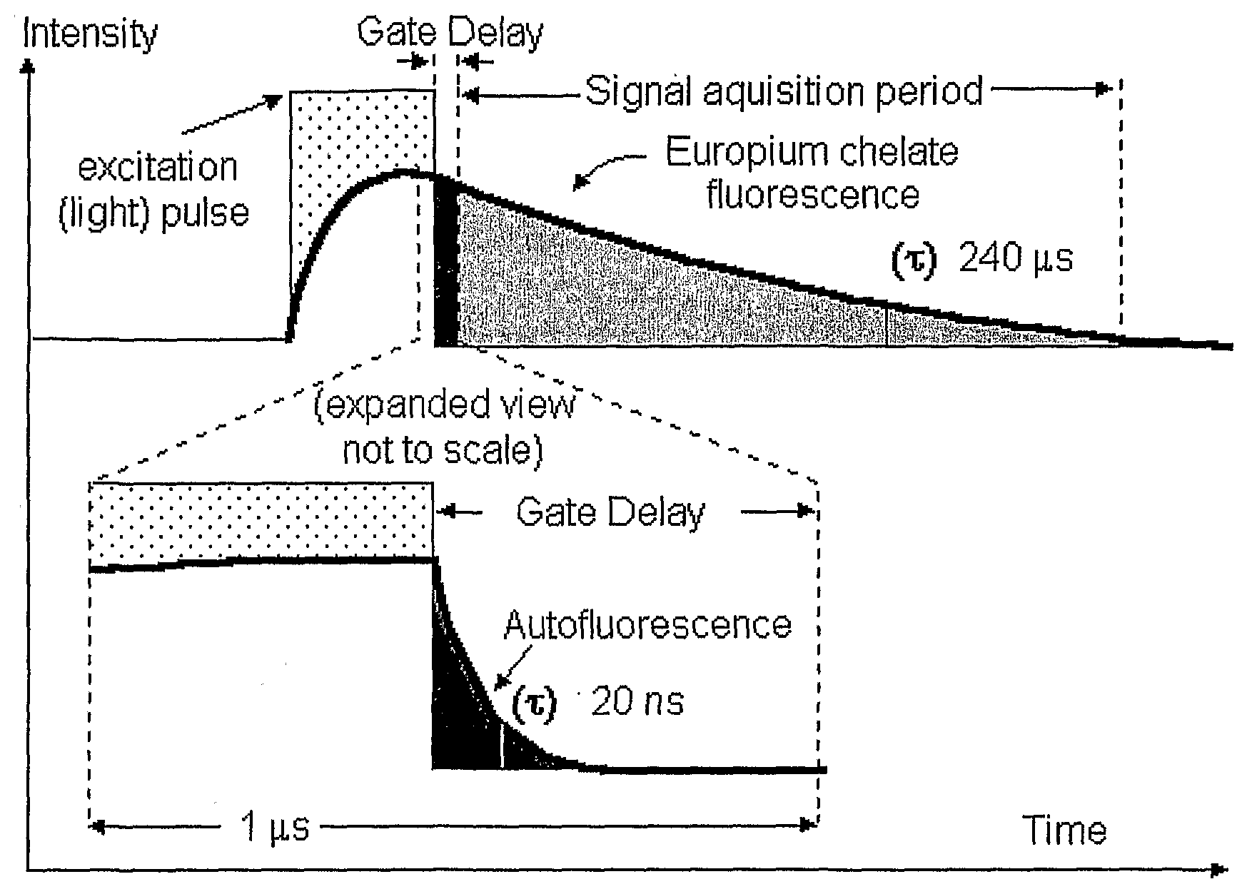
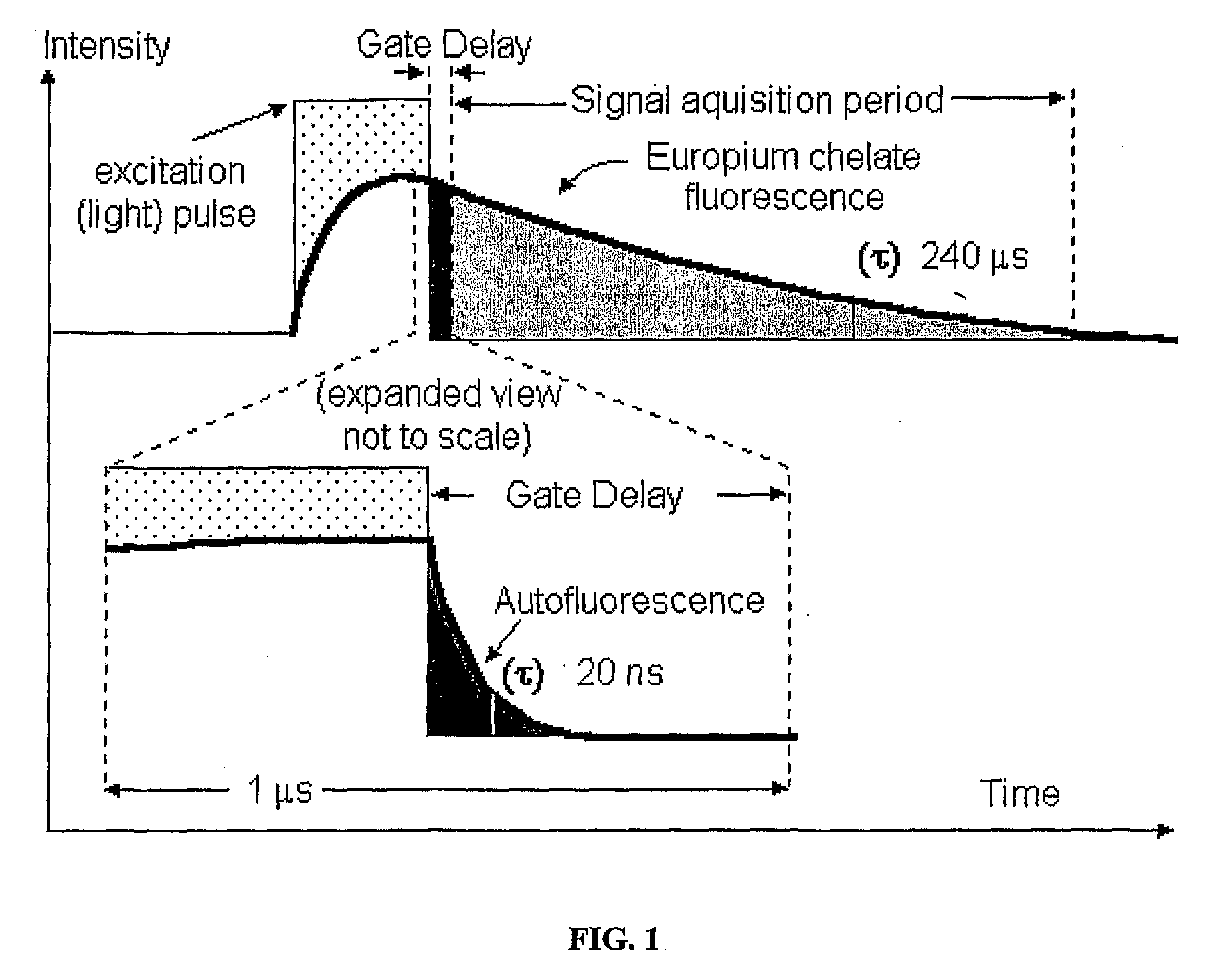
[0152]The recent availability of light emitting diodes (LEDs) that emit at 365 nm (FWHM of 10 nm), prompted evaluation for their suitability in time-resolved fluorescence applications. LEDs are easily powered and have the advantage of nanosecond switching speeds, however the emission wavelength longer than is optimal (337 nm). Nevertheless, a UV LED was employed as the excitation source to replace the flashlamp in a lab-built TRFM. The LED (type NCCU033, rated at 100 mW; Nichia Corp, Japan) was adapted to fit the filter-box housing of a fluorescence microscope (Axioscop; Zeiss Instruments) and used to excite fluorescence from fluorescently labelled Giardia cysts spiked into a 10,000:1 water concentrate that was strongly autofluorescent. The LED was pulsed for a 100 μs duration at a repetition rate of 500 Hz with a peak current of 793 mA. The narrow line width of the LED UV emission enabled removal of the excitation filter and emission filter, resulting in a significant improvement i...


PUM

PropertyMeasurementUnit
optical output poweraaaaaaaaaa
fluorescence lifetimeaaaaaaaaaa

Abstract

A fluorescence detection system comprises a light source (22), dichroic mirror (32), excitation port (16), emission port (14), and a detector. The light source (22) is, for example, a pulsed ultraviolet LED, with a light emission that decays sufficiently rapidly to permit gated detection of fluorescence from a fluorescently-labelled species, at a time when it is distinguishable from autofluorescence. The detector is, for example, an electron multiplying CCD, with high gain on-chip amplification. A circuit (26) may be used to control a repeating cycle of (i) generation of a 20-200 microsecond UV. pulse; (ii) a gate delay of 1-5 microseconds; and (iii) a 10-800 microsecond detection period. This allows time-resolved-fluorescence-microscopy with real time or near real time operation.

Description

TECHNICAL FIELD[0001]The present invention relates to fluorescence detection systems, particularly time resolved fluorescence detection systems.BACKGROUND OF THE INVENTION[0002]Various types of immunoassay involve attaching fluorescent labels either directly or indirectly to a species of interest, for example a microorganism. Animal, plant and microbial cells contain significant amounts of aromatic compounds, many of which are intrinsically fluorescent (autofluorescent) when excited at an appropriate wavelength. The range of fluorescent substances of biological origin described in the biochemical literature is large and includes chlorophyll, haemoglobin and protein. When these autofluorescent materials have high quantum yields (typically >0.02) they can present a problem of spurious fluorescence against which fluorescent labels of interest must be detected.[0003]Autofluorescence can occur throughout the visible spectrum and is typically a short-lived phenomena with a lifetime (τ)...

Claims


Application Information

Patent Timeline
Patent Type & Authority Applications(United States)
IPC IPC(8): G01N21/64
CPCG01N21/6408G01N21/6458
Inventor CONNALLY, RUSSELLPIPER, JAMES AUSTIN
Owner MACQUARIE UNIV
Why Eureka
Try Eureka