Thus, complex processes are required for production of PArT.
However, this technique is problematic in that it requires special and complex equipment or methods as well as a long period of time.
Moreover, the technique is also problematic in that it requires an enormous a
mount of energy for repeating heating and cooling so many times. Furthermore, such
solid phase
polymerization is also problematic in that a large amount of
powder polymer that is hardly melted is generated during the polymerization, and in that the thus generated
polymer plays a role in
foreign matter, which might inhibit molding or might deteriorate the quality of a molded article, such as in terms of surface properties, resistance, or transparency.
Still further, it is also problematic in that since strict conditions such as a high temperature or high shearing are required when a pellet with a high degree of
crystallinity is subjected to melt
processing, although a high-quality
polymer can be produced, the quality of a molded article is then significantly deteriorated.
However, since high polymerization brings on a high
viscosity, it becomes more difficult to eliminate alkylene glycol.
When polymerization is carried out in a high vacuum, since the rotary drive portion cannot be completely sealed, inflow of a trace amount of air cannot be prevented, and polymer coloration thereby becomes inevitable.
Even when a sealing solution is used to prevent such inflow of air, mixing of the sealing solution is inevitable, and thus, the quality of a polymer is inevitably deteriorated.
Moreover, even when high sealing properties are kept at the beginning of the operations, the sealing properties might be decreased during long-term operations.
Thus, there is also a serious problem regarding maintenance.
Furthermore, it is also difficult to reduce the content of impurities such as
acetaldehyde, which is emphasized especially in the field of beverage containers.
In this technique, however, since an extruder with a vent is used in deaeration, a
polyester with a high polymerization degree has an excessively high
viscosity, and
acetaldehyde cannot be sufficiently reduced.
A technique of adding a
phosphate-containing compound to prevent coloration has also been proposed, but it cannot sufficiently enhance quality.
However, according to the studies of the present inventors, since a horizontal biaxial
agitator-type reactor is used as a
polymerization reactor in this technique, a long period of time is required for high polymerizetion.
Further, inflow of the air from the axial sealing portion causes significant coloration.
In addition, since an industrial-scale reactor causes a great depth of liquid, high polymerization is further difficult, and it also becomes impossible to reduce
acetaldehyde.
It is also extremely difficult to uniformly inject into a
polyester molten body
inert gas in an amount sufficient for deaeration in a horizontal reactor on an
industrial scale.
However, if a common horizontal double axis
agitator-type reactor was used in this technique, a long period of time would be required for high polymerization, and further, inflow of the air from an axial sealing portion would cause significant coloration.
Further, since this technique requires special auxiliary equipment such as a mixer or flash tank as well as a reactor, the processes become complicated.
Furthermore, since such a mixer or flash tank has a space where a polymer can remain for a long time,
pyrolysis locally progresses, and a depleted polymer that is significantly
colored is mixed into a product.
Therefore, long-term polymerization is required to achieve a high polymerization degree, and inflow of the air from an axial sealing portion causes significant coloration.
A devolatilizer for eliminating acetaldehyde, etc. is essential in this method, but a polymer is required to remain in such a devolatilizer for a further period of time, so that the product is deteriorated in color and that the production cost also increases.
However, the use of a large amount of such an acetaldehyde
scavenger causes problems such as generation of
odor and coloration derived from the
scavenger.
As stated above, the conventional melt polymerization techniques can reduce volatile impurities such as acetaldehyde, but they cannot achieve a PArT molded article, which has a high polymerization degree and a good
hue.
In this technique, since recirculation of the fallen polymer results in deterioration of the quality of the produced
polyester, polymerization is completed by one-pass operation.
However, since it is extremely difficult to keep a sufficient polymerization time by such a method, it is also extremely difficult to obtain a polymer with a high polymerization degree.
This is problematic in that the quality of the obtained polymer is drastically fluctuated; and in that condensates with a low molecular weight scattered from the filaments contaminate the
nozzle surface, and it becomes difficult for the filaments to be injected directly below from the
nozzle due to such
contamination, and as a result, the filaments come into contact with one another and are
cut off, or they are gathered to become a thick filament and it is then fallen, so that it prevents the reaction.
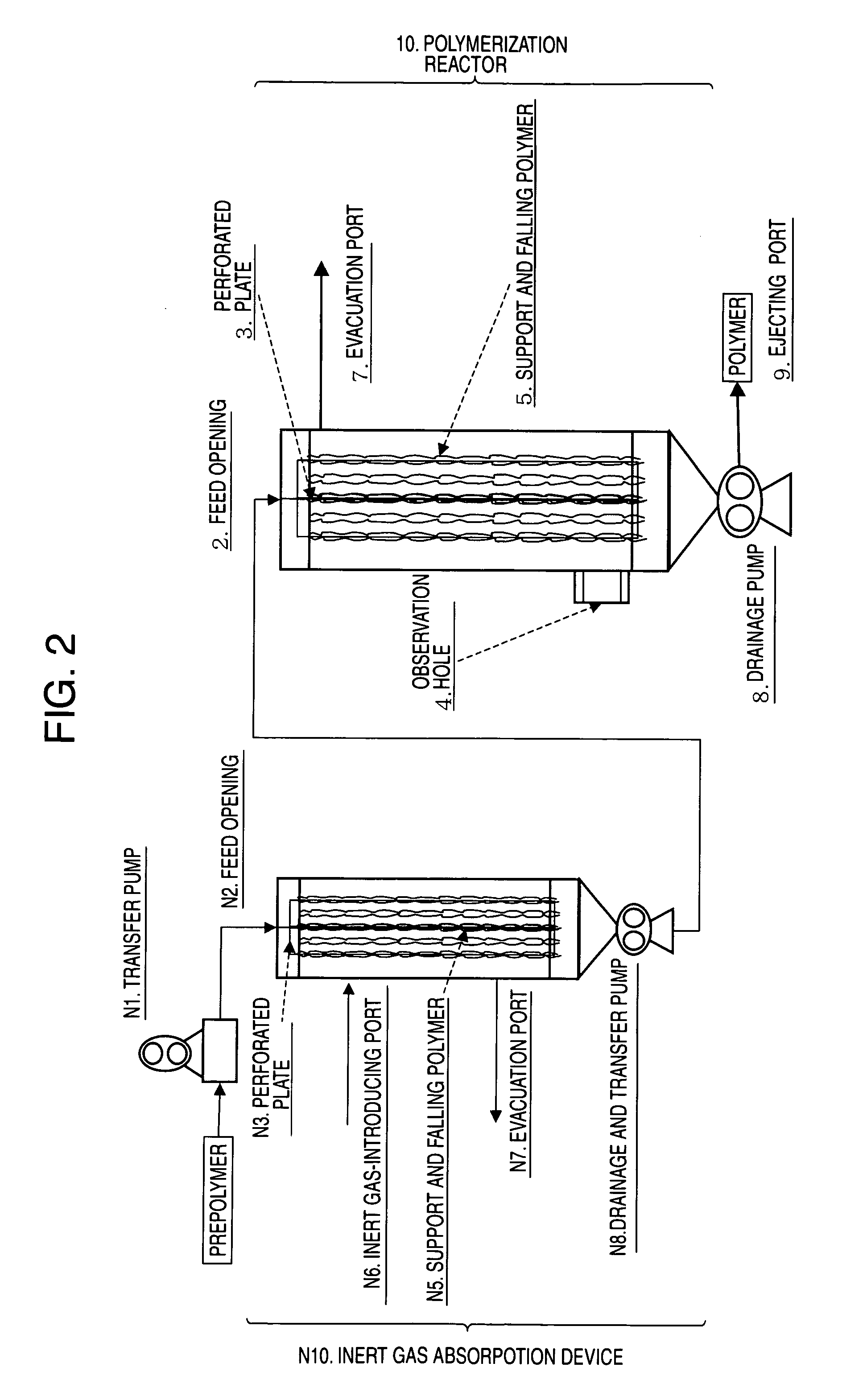
However, according to the studies of the present inventors, EG generated as a by-product cannot be eliminated from the
reaction product at a sufficient rate in such an
atmosphere where
inert gas is circulated.
Thus, a polymer with a high polymerization degree required for beverage containers cannot be obtained.
However, according to the studies of the present inventors, a polymer with a polymerization
degree of interest cannot be obtained by directly applying the above described method in industrial-scale equipment.
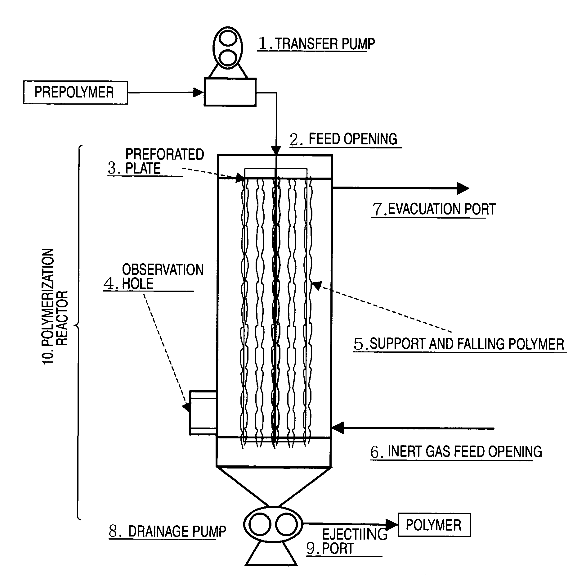
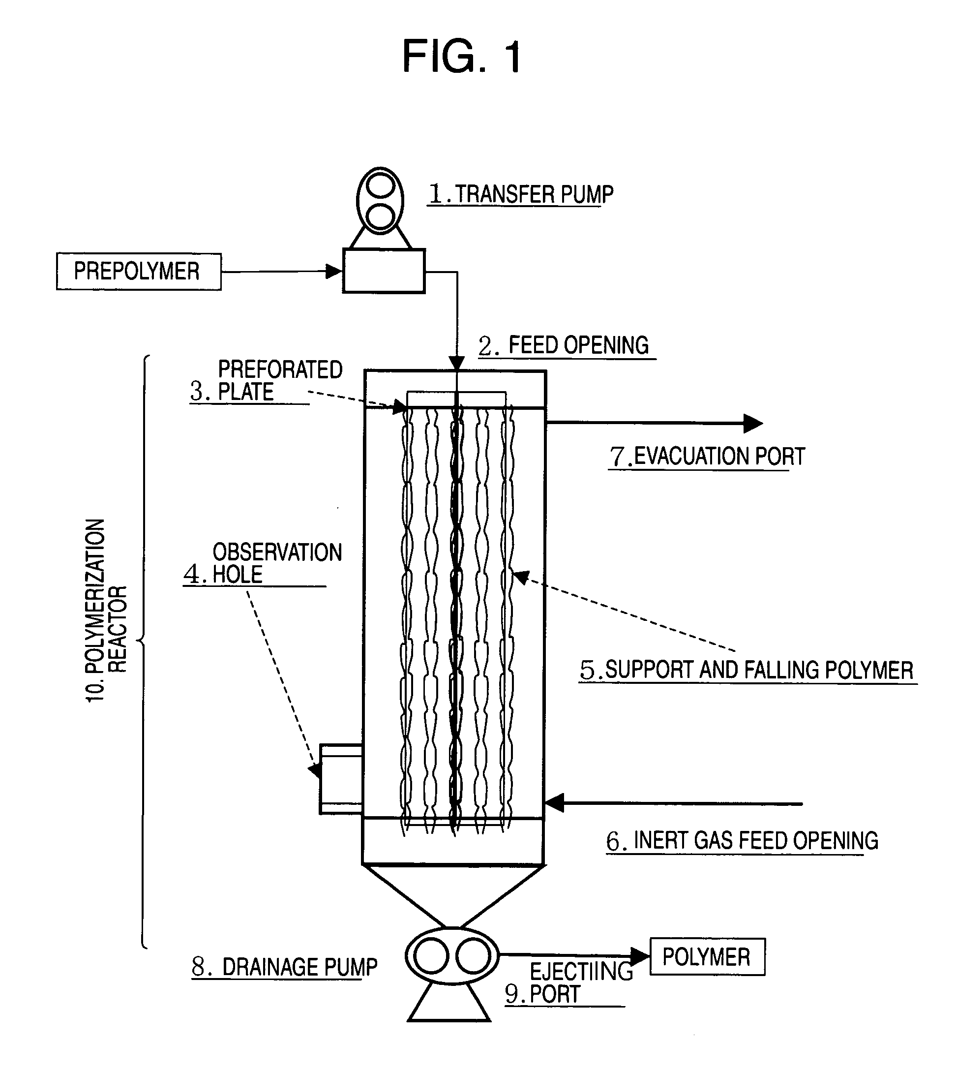
Moreover, a polymer discharged from a perforated plate or the like intensively foams, and it contaminates the wall of the reactor provided with the support and the
nozzle surface.
Such contaminants are decomposed, modified, or
colored during long-term operations, and these degradation products are mixed into a polymer, so that the quality of a product deteriorates.
However, according to the studies of the present inventors, a polymer with a high polymerization degree cannot be obtained by applying the above method.
When the amount of a prepolymer supplied is decreased to improve a polymerization velocity, a drift (biased flow) of the prepolymer occurs, and thus, a high-quality polymer cannot be obtained.
Hence, the conventional gravity falling-type melt polymerization techniques (Patent Documents 9 to 14) could not provide a method of industrially stably producing a high-quality PArT having a high polymerization degree with good productivity, which can be substituted for the
solid phase polymerization technique.
In addition, these gravity falling-type melt polymerization techniques give no suggestion regarding a technique of obtaining a molded article containing small quantities of low molecular weight volatile substances such as acetaldehyde.

