Furnace atmosphere activation method and apparatus

a technology of activation method and apparatus, applied in plasma technique, solid-state diffusion coating, energy-based chemical/physical/physico-chemical processes, etc., can solve the problems of environmental air leakage, slow kinetic reaction or stability, and risk of damaging the loaded metallic material or work par

Inactive Publication Date: 2008-11-20
AIR PROD & CHEM INC
View PDF16 Cites 38 Cited by
  • Summary
  • Abstract
  • Description
  • Claims
  • Application Information

AI Technical Summary

Benefits of technology

[0018]In one respect, the invention comprises an activated gas injector for use with a controlled atmosphere reactor having a reactor chamber. The activated gas injector includes a shell that defines an activation chamber having an outlet, a first gas inlet which is adapted to be connected to a supply of a first gas and to introduce the first gas into the activation chamber, a first electrode that extends into the activation chamber and terminates within the activation chamber, a power supply connected to the first electrode which, when energized, provides an average voltage output at least 1 kV and an average current output of less than 10 A, and a second electrode that is exposed to the activation chamber and provides a ground potential with respect to the first electrode. The first and second electrodes are positioned so that electrical discharges occur between the first electrode and the second electrode when the power supply is energized, the area in which the electrical discharges occur defining an electrical discharge zone. The activation chamber, the first electrode, the second electrode, and the first gas inlet are configured so that the first gas is drawn through the electrical discharge zone before exiting the activation chamber through the outlet.
[0019]In another respect, the invention comprises, a controlled-atmosphere reactor system including a reactor chamber adapted to accommodate a workload to be treated, the reactor chamber having an exhaust, at least one heat source being collectively capable of elevating the reactor chamber to a temperature of at least 90 degrees C., and at least one gas injector. Each of the gas injectors include a shell defining an activation chamber having an outlet that is in flow communication with the reactor chamber, a first gas inlet which is adapted to be connected to a supply of a first gas and is positioned to introduce the first gas into the activation chamber, a first electrode

Problems solved by technology

There are three common process control problems when using atmospheres in elevated temperature thermal treatments: (1) slow kinetic reactions or stability of gas injected, (2) surface condition of material of work part loaded to furnace, and (3) environmental air leakage.
For example, CH4 injected into the furnace for carburizing may slowly react with and dispose of undesired oxygen (O2) or CO2 and/or may shift the thermodynamic potential of furnace atmosphere, and/or may dissociate and react only marginally, unless furnace temperature is very high; however, the high temperature poses a risk of damaging the loaded metallic material or work part.
Also, the material or work surface loaded into the furnace may be covered with a thick film of oxide, rust, or water-based oily residues, and the reactivity of the original atmosphere may turn out to be insufficient for this film removal within the desired treatment time and temperature range.
Finally, furnace air leaks and the other O2-containing sources of contamination may require additions of reducing and, sometimes, carburizing gases to the atmosphere, even if the most desired atmosphere would be an inert environment to parts for specific thermal transformation processes, that is, one without reducing and/or carburizing gases.
Such in-situ geftering techniques are limited by many process considerations.
With these low temperatures and concentrations, the gettering and oxide removal effect of H2 is marginal due to slow reduction kinetics.
Similar limitations can be found in carburizing of steel parts with natural gas, in the absence of endothermic, CO-containing atmospheres.
For

Method used


Image

  • Furnace atmosphere activation method and apparatus
  • Furnace atmosphere activation method and apparatus
  • Furnace atmosphere activation method and apparatus

Examples


second embodiment

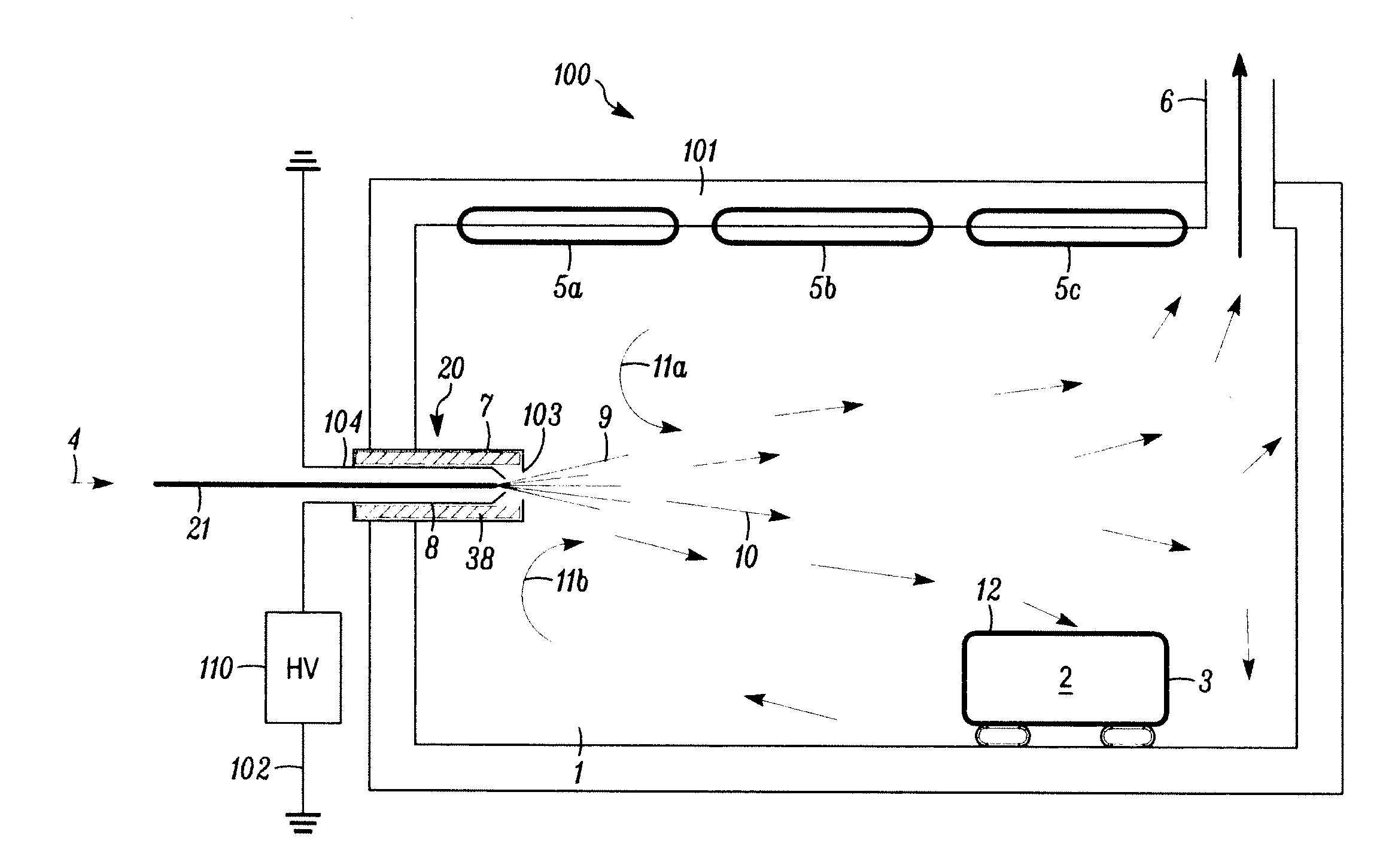
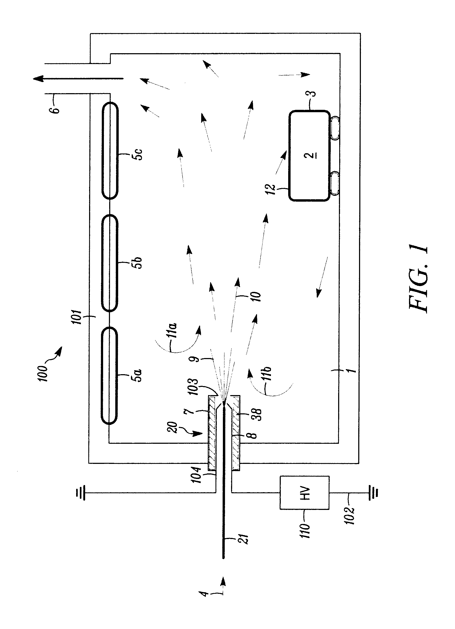
[0032]FIGS. 2A & 2B show an activated gas injector 120 which includes a cylindrical cup 113 having an open end 122, a supply pipe 121 and an electrode 108. The internal volume defined by the cup 113 and the open end 122 is the activation chamber for this embodiment. Like the electrode 8 shown in FIG. 1, the electrode 108 is preferably connected to a high-voltage, low-current power supply (not shown). The electrode 108 extends into the cup 113 along its central axis, terminates inside the cup 113 (i.e., does not extend past the open end 122 of the cup 113) and is insulated from the cup 113, preferably by a ceramic, high-temperature-resistant insulator 138. The cup 113 is preferably made from a conductive metal and is grounded by a ground lead 115.

[0033]When operated, a process gas stream 114 is injected into the cup 113 from an external source via an inlet 140 from a gas supply pipe 121. The gas supply pipe 121 and the inlet 140 is preferably positioned tangent to the perimeter of th...

third embodiment

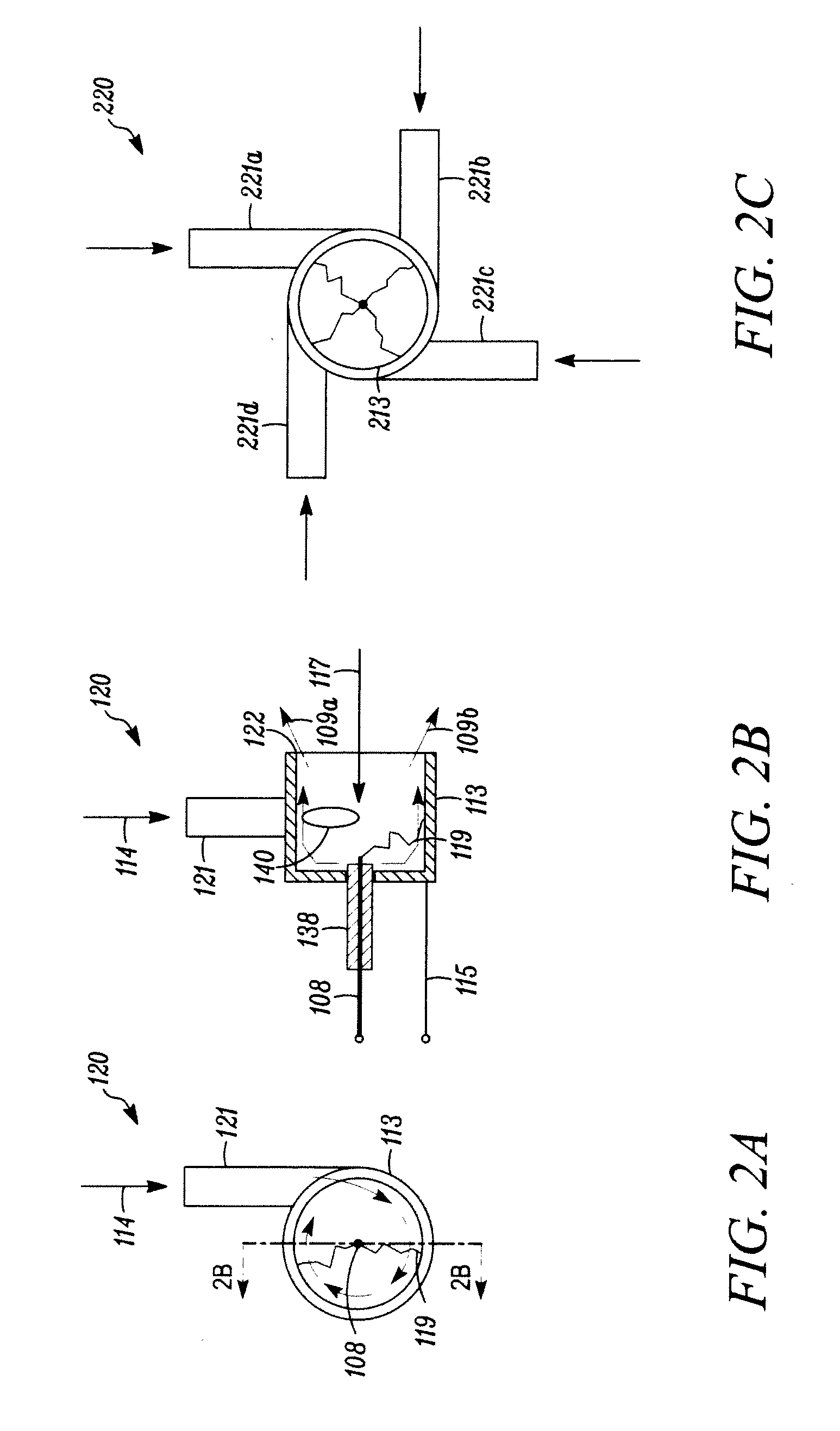
[0035]FIG. 2C shows the activated gas injector shown in FIGS. 2A & 2B. In this embodiment, the activated gas injector 220 includes multiple tangential injection ports 221a, 221b, 221c, 221d for the process gas, which may provide assuring a more uniform swirling inside the cup 213.

[0036]FIGS. 3A, 3B and 3C show three additional embodiments of the activated gas injector. The activated gas injector 320 depicted in FIG. 3A is identical to activated gas injector 120 (shown in FIGS. 2A & 2B), except that the open end 322 of the injector cup 313 is partially-covered by a lid 330 having an axial hole 331 formed therein. As compared to the activated gas injector 120, the activated gas injector 320 reduces aspiration of furnace atmosphere gas into the injector cup 313 and increases the velocity of the electric discharge activated stream 309 as it exits the injector cup 313. As a result, increased aspiration and entrainment of the furnace gases with the electric discharge-activated stream 309 ...


PUM

PropertyMeasurementUnit
Pressureaaaaaaaaaa
Angleaaaaaaaaaa
Currentaaaaaaaaaa

Abstract

A gas injector including in which a gas is passed through high-voltage/low-current electrical discharges before being discharged into the chamber of a thermal treatment furnace. The electrical activation of the gas accelerates desirable reactions between the gas, gases in the furnace chamber, and the chamber workload. Preferably, a hot electrode is electrically charged and the other parts of the gas injector and the furnace are grounded.

Description

CROSS REFERENCE TO RELATED APPLICATION(S)[0001]This application claims the benefit of U.S. Provisional Application No. 60 / 928,385, filed on May 9, 2007, which is incorporated by reference as if fully set forth.BACKGROUND[0002]The present invention concerns elevated temperature, thermal treatments of metallic or cermet materials and work parts in furnaces or reactors using reactive atmospheres. The atmospheres and treatments in the scope of invention include carburizing, nitriding, carbonitriding, nitrocarburizing, boronizing, bright annealing or oxide reduction, reducing atmospheres for brazing, soldering and sintering, carbon potential atmospheres for neutral heat treating of phase transformation alloys, solutionizing, aging, spheroidizing, hardening, stress relieving, normalizing, inert annealing, and the like. The components of said atmospheres may include nitrogen (N2), hydrogen (H2), hydrocarbon gases (HC) such as methane (CH4), acetylene (C2H2), ethylene (C2H4), propane (C3H8)...

Claims


Application Information

Patent Timeline
IPC IPC(8): C23C8/68B01J19/08C23C8/20C23C8/24C23C8/30C23C8/36
CPCH05H1/48C23C16/50C23C16/00H01J37/32
Inventor ZURECKI, ZBIGNIEWKNORR, JR., ROBERT ELLSWORTHGREEN, JOHN LEWIS
Owner AIR PROD & CHEM INC
Why Eureka
Try Eureka